PROCEDURE
- Click here
INSTALL INSTRUMENT PANEL SAFETY PAD SUB-ASSEMBLY
-
When installing a new instrument panel safety pad sub-assembly:
-
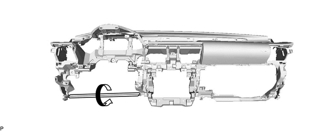
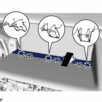
Immediately before installing the instrument panel safety pad sub-assembly, twist and cut off the portion as shown in the illustration.
-
-
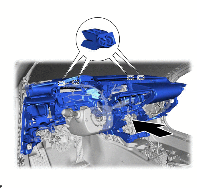
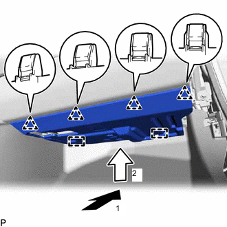
Engage the 4 guides to temporarily install the instrument panel safety pad sub-assembly as shown in the illustration.
Note:
-
Do not damage the instrument panel safety pad sub-assembly.
-
Do not allow the wire harnesses to interfere with the surrounding parts.
-
-
Install the instrument panel safety pad sub-assembly with the 13 bolts <A>, 2 bolts <B> and nut <E>.
Bolt<B> 20 N*m 204 kgf*cm 15 ft.*lbf -
Engage each clamp.
-
Connect each connector.
-
Engage the 2 claws to connect the room temperature sensor.
-
- Click here
CONNECT NO. 2 INSTRUMENT PANEL WIRE
- Click here
INSTALL INSTRUMENT CLUSTER FINISH PANEL ORNAMENT
-
Engage the 3 clips and 2 claws to install the instrument cluster finish panel ornament.
-
- Click here
INSTALL FRONT NO. 2 SPEAKER ASSEMBLY (for RH Side)
- Click here
INSTALL NO. 2 INSTRUMENT PANEL SPEAKER PANEL SUB-ASSEMBLY
-
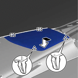
Engage the 2 guides as shown in the illustration.
-
Engage the 2 clips to install the No. 2 instrument panel speaker panel sub-assembly.
-
- Click here
INSTALL FRONT PILLAR GARNISH RH
- Click here
INSTALL FRONT NO. 3 SPEAKER ASSEMBLY
- Click here
INSTALL INSTRUMENT CLUSTER FINISH PANEL ASSEMBLY
-
Engage the 4 claws and 4 clips to install the instrument cluster finish panel assembly.
-
- Click here
INSTALL FRONT NO. 2 SPEAKER ASSEMBLY (for LH Side)
- Click here
INSTALL NO. 1 INSTRUMENT PANEL SPEAKER PANEL SUB-ASSEMBLY
-
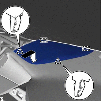
Engage the 2 guides as shown in the illustration.
-
Engage the 2 clips to install the No. 1 instrument panel speaker panel sub-assembly.
-
- Click here
INSTALL FRONT PILLAR GARNISH LH
- Click here
INSTALL MULTI-DISPLAY ASSEMBLY WITH BRACKET
- Click here
INSTALL INSTRUMENT CLUSTER FINISH PANEL SUB-ASSEMBLY
-
Engage the 3 guides as shown in the illustration.
-
Engage the 3 claws to install the instrument cluster finish panel sub-assembly.
-
- Click here
INSTALL CENTER INSTRUMENT PANEL REGISTER ASSEMBLY
-
Connect the connector.
-
Engage the 4 clips and 4 claws to install the center instrument panel register assembly.
-
- Click here
INSTALL AIR CONDITIONING CONTROL ASSEMBLY
- Click here
INSTALL RADIO RECEIVER ASSEMBLY WITH BRACKET
- Click here
INSTALL NO. 2 INSTRUMENT PANEL REGISTER ASSEMBLY
-
Engage the 2 clips and 2 claws.
-
Engage the claw to install the No. 2 instrument panel register assembly.
-
- Click here
INSTALL GLOVE COMPARTMENT DOOR ASSEMBLY
-
Connect each connector.
-
Engage the connector clamp.
-
Engage the 5 claws.
-
Install the 2 screws <C>.
-
Open the glove compartment door assembly.
-
Install the glove compartment door assembly with the 3 screws <C>.
-
Close the glove compartment door assembly.
-
- Click here
INSTALL LOWER NO. 2 INSTRUMENT PANEL AIRBAG ASSEMBLY
- Click here
INSTALL NO. 2 INSTRUMENT PANEL UNDER COVER SUB-ASSEMBLY
-
Connect each connector.
-
Engage the 2 guides and 4 clips as indicated by the arrows, in the order shown in the illustration to install the No. 2 instrument panel under cover sub-assembly.
-
- Click here
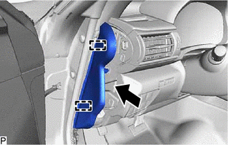
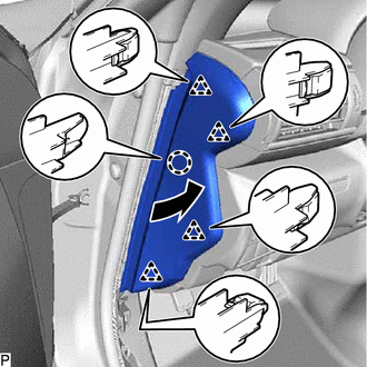
INSTALL INSTRUMENT SIDE PANEL RH
-
w/ Airbag Cut Off Switch:
-
Connect the connector.
-
-
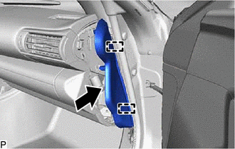
Engage the 2 guides as shown in the illustration.
-
Engage the claw and 4 clips to install the instrument side panel RH as shown in the illustration.
-
- Click here
INSTALL FRONT DOOR OPENING TRIM COVER RH
- Click here
INSTALL FRONT DOOR SCUFF PLATE RH
- Click here
ALIGN FRONT WHEELS FACING STRAIGHT AHEAD
- Click here
INSPECT AND ADJUST SPIRAL CABLE WITH SENSOR SUB-ASSEMBLY
- Click here
INSTALL STEERING WHEEL ASSEMBLY
w/ Lane Departure Alert System:
w/o Lane Departure Alert System:
- Click here
INSTALL HORN BUTTON ASSEMBLY
- Click here
INSTALL NO. 1 INSTRUMENT PANEL REGISTER ASSEMBLY
-
Engage the 2 clips and 2 claws to install the No. 1 instrument panel register assembly.
-
- Click here
INSTALL TELEMATICS TRANSCEIVER (w/ Telematics Transceiver)
- Click here
INSTALL COMBINATION METER ASSEMBLY
- Click here
INSTALL METER HOOD SUB-ASSEMBLY
-
Connect the connector.
-
Engage the 2 claws, 7 clips and 3 guides to temporarily install the meter hood sub-assembly as shown in the illustration.
-
Engage the 4 clips and 2 claws to install the meter hood sub-assembly.
-
- Click here
INSTALL LOWER NO. 1 INSTRUMENT PANEL AIRBAG ASSEMBLY
- Click here
INSTALL SKID CONTROL BUZZER (w/ Pre-collision System)
- Click here
INSTALL LOWER INSTRUMENT PANEL FINISH PANEL SUB-ASSEMBLY
-
Connect each connector.
-
Engage the 5 claws, 7 clips and guide to install the lower instrument panel finish panel sub-assembly.
-
- Click here
CONNECT HOOD LOCK CONTROL LEVER SUB-ASSEMBLY
-
Engage the claw and 2 guides to connect the hood lock control lever sub-assembly.
-
- Click here
INSTALL NO. 1 INSTRUMENT PANEL UNDER COVER SUB-ASSEMBLY
-
Connect each connector.
-
Engage the connector clamp.
-
Engage the 3 clips.
-
Install the No. 1 instrument panel under cover sub-assembly with the 2 screws <C>.
-
- Click here
INSTALL INSTRUMENT SIDE PANEL LH
-
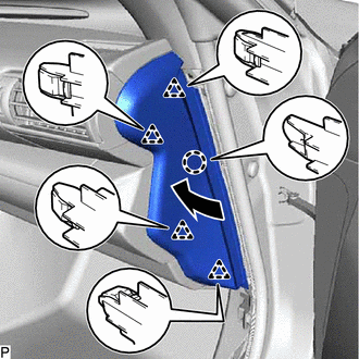
Engage the 2 guides as shown in the illustration.
-
Engage the claw and 4 clips to install the instrument side panel LH as shown in the illustration.
-
- Click here
INSTALL FRONT DOOR OPENING TRIM COVER LH
- Click here
INSTALL FRONT DOOR SCUFF PLATE LH
- Click here
INSTALL CONSOLE BOX ASSEMBLY
- Click here
CONNECT CABLE TO NEGATIVE BATTERY TERMINAL
Note:When disconnecting the cable, some systems need to be initialized after the cable is reconnected.
- Click here
CHECK STEERING WHEEL CENTER POINT
- Click here
PERFORM DIAGNOSTIC SYSTEM CHECK
- Click here
INSPECT SRS WARNING LIGHT
- Click here
PERFORM YAW RATE SENSOR AND ROLL RATE AND VERTICAL ACCELERATION SENSOR ZERO POINTS CALIBRATION AND STORE SYSTEM INFORMATION
- Click here
CUSTOMIZE POWER TILT AND POWER TELESCOPIC STEERING COLUMN SYSTEM (for Power Tilt and Power Telescopic Steering Column)