PROCEDURE
- Click here
INSTALL COOLER CONDENSER ASSEMBLY
-
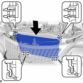
Engage the 2 guides to install the cooler condenser assembly as shown in the illustration.
Note:Do not damage the condenser or radiator when installing the cooler condenser assembly.
Tip:If a new cooler condenser assembly is installed, add compressor oil to the condenser as follows.
Capacity Add 40 cc (1.35 fl. oz) Refrigerant Compressor Oil HFC-134a (R134a) ND-OIL 8 or equivalent HFO-1234yf (R1234yf) ND-OIL 12 or equivalent -
Engage the 2 claws.
-
- Click here
CONNECT NO. 1 COOLER REFRIGERANT DISCHARGE HOSE
-
Remove the vinyl tape from the No. 1 cooler refrigerant discharge hose and the connecting part of the cooler condenser assembly.
-
Sufficiently apply compressor oil to a new O-ring and the fitting surface of the No. 1 cooler refrigerant discharge hose.
Refrigerant Compressor Oil HFC-134a (R134a) ND-OIL 8 or equivalent HFO-1234yf (R1234yf) ND-OIL 12 or equivalent -
Install the O-ring to the No. 1 cooler refrigerant discharge hose.
-
Connect the No. 1 cooler refrigerant discharge hose to the cooler condenser assembly with the bolt.
5.4 N*m 55 kgf*cm 48 in.*lbf
-
- Click here
CONNECT LIQUID PIPE SUB-ASSEMBLY
-
Remove the vinyl tape from the liquid pipe sub-assembly and the connecting part of the cooler condenser assembly.
-
Sufficiently apply compressor oil to a new O-ring and the fitting surface of the liquid pipe sub-assembly.
Refrigerant Compressor Oil HFC-134a (R134a) ND-OIL 8 or equivalent HFO-1234yf (R1234yf) ND-OIL 12 or equivalent -
Install the O-ring to the liquid pipe sub-assembly.
-
Connect the liquid pipe sub-assembly to the cooler condenser assembly with the 2 bolts.
5.4 N*m 55 kgf*cm 48 in.*lbf
-
- Click here
INSTALL UPPER RADIATOR SUPPORT
- Click here
CONNECT ENGINE ROOM MAIN WIRE
- Click here
INSTALL HOOD LOCK ASSEMBLY
- Click here
CONNECT HOOD LOCK CONTROL CABLE ASSEMBLY
- Click here
INSTALL HOOD LOCK RELEASE LEVER PROTECTOR
- Click here
INSTALL INLET NO. 1 AIR CLEANER
- Click here
INSTALL MILLIMETER WAVE RADAR SENSOR ASSEMBLY (w/ Dynamic Radar Cruise Control System)
- Click here
CHARGE AIR CONDITIONING SYSTEM WITH REFRIGERANT (for HFC-134a(R134a))
- Click here
CHARGE AIR CONDITIONING SYSTEM WITH REFRIGERANT (for HFO-1234yf(R1234yf))
- Click here
WARM UP ENGINE (for HFC-134a(R134a))
- Click here
WARM UP ENGINE (for HFO-1234yf(R1234yf))
- Click here
INSPECT FOR REFRIGERANT LEAK (for HFC-134a(R134a))
- Click here
INSPECT FOR REFRIGERANT LEAK (for HFO-1234yf(R1234yf))
- Click here
ADJUST HOOD SUB-ASSEMBLY