AIR CONDITIONING UNIT INSTALLATION

PROCEDURE
-
INSTALL AIR CONDITIONING UNIT ASSEMBLY
-
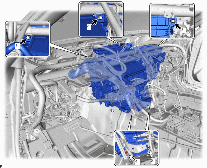
Temporarily install the air conditioning unit assembly to the instrument panel reinforcement assembly with the 3 bolts and 2 screws.
-
-
INSTALL INSTRUMENT PANEL REINFORCEMENT ASSEMBLY WITH AIR CONDITIONING UNIT
Note
-
Be sure to support the air conditioning unit assembly when installing it because failure to do so may cause the bracket of the air conditioning unit assembly to break.
-
When installing the air conditioning unit assembly, eliminate static electricity by touching the vehicle body to prevent the components from being damaged.
-
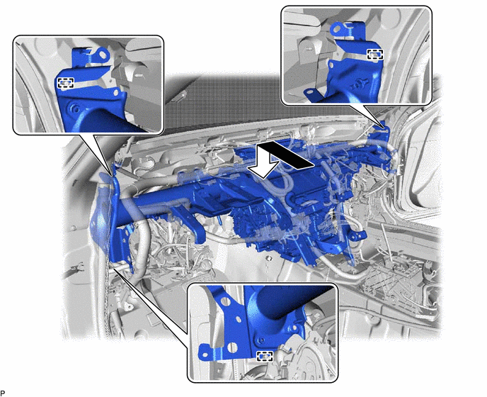
Engage the 3 guides to temporarily install the instrument panel reinforcement assembly with air conditioning unit as shown in the illustration.
-
Using SST, temporarily install the 8 bolts and nut as shown in the illustration.
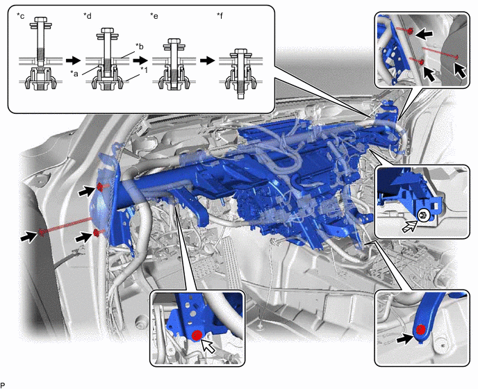
*1 Instrument Panel Reinforcement Assembly - - *a Movable Collar *b Vehicle Body *c Step 1 *d Step 2 *e Step 3 *f Step 4 
Bolt (A) 
Bolt (B) 
Nut - - - SST
- 09812-00010
-
Tighten the 7 bolts (A).
- Torque:
- 20 N*m { 204 kgf*cm, 15 ft.*lbf }
-
Tighten the bolt (B).
- Torque:
- 21 N*m { 214 kgf*cm, 15 ft.*lbf }
-
Tighten the nut.
- Torque:
- 9.8 N*m { 100 kgf*cm, 87 in.*lbf }
-
Install the 3 bolts.
- Torque:
- 9.8 N*m { 100 kgf*cm, 87 in.*lbf }
-
Install the 3 hole plugs.
-
Engage each clamp.
-
Connect each connector.
-
Connect the bracket with the bolt.
-
Connect the 3 earth wires with the 3 bolts.
- Torque:
- 8.4 N*m { 86 kgf*cm, 74 in.*lbf }
-
-
FULLY TIGHTEN AIR CONDITIONING UNIT ASSEMBLY
-
for LHD:
-
Tighten the 3 bolts and 2 screws.
Bolt Screw - Torque:
- 9.8 N*m { 100 kgf*cm, 87 in.*lbf }
Note
Tighten the bolts and screws in the order shown in the illustration to install the air conditioning unit assembly.
-
-
for RHD:
-
Tighten the 3 bolts and 2 screws.
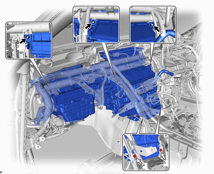
Bolt Screw - Torque:
- 9.8 N*m { 100 kgf*cm, 87 in.*lbf }
Note
Tighten the bolts and screws in the order shown in the illustration to install the air conditioning unit assembly.
-
-
-
INSTALL INSTRUMENT PANEL SAFETY PAD CAP
-
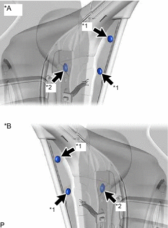
*A for LH Side *B for RH Side *1 Instrument Panel Safety Pad Cap (A) *2 Instrument Panel Safety Pad Cap (B) Install 4 new instrument panel safety pad caps (A) and 2 instrument panel safety pad caps (B).
-
-
INSTALL NO. 2 INSTRUMENT PANEL TO FLOOR BRACE
-
Engage the 2 guides.
-
Install the No. 2 instrument panel to floor brace with the 3 bolts.
- Torque:
- 20 N*m { 204 kgf*cm, 15 ft.*lbf }
-
-
INSTALL NO. 1 CONSOLE BOX DUCT
-
Install the No. 1 console box duct with the 2 clips.
-
Engage the clamp.
-
-
INSTALL REAR NO. 1 AIR DUCT
-
Install the rear No. 1 air duct.
-
Engage the 2 clamps to connect the wire harness.
-
-
INSTALL FRONT FLOOR SILENCER PAD LH
-
Install the front floor silencer pad LH.
-
-
INSTALL REAR NO. 2 AIR DUCT
-
Engage the 4 claws to install the rear No. 2 air duct.
-
Install the front floor carpet assembly to the original position as shown in the illustration.
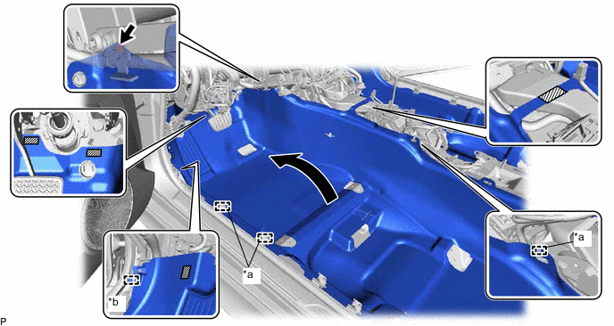
*a Guide *b Clamp 
Fastener - - -
Engage each fastener and the clamp.
-
Engage the 3 guides.
-
Install the clip.
-
Engage the 2 claws.
-
-
INSTALL REAR NO. 3 AIR DUCT
-
Install the rear No. 3 air duct.
-
Engage the 2 clamps to connect the wire harness.
-
-
INSTALL FRONT FLOOR SILENCER PAD RH
-
Install the front floor silencer pad RH.
-
-
INSTALL REAR NO. 4 AIR DUCT
-
Engage the 4 claws to install the rear No. 4 air duct.
-
Install the front floor carpet assembly to the original position as shown in the illustration.
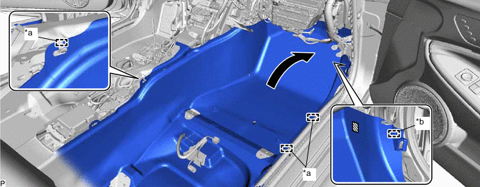
*a Guide *b Clamp Fastener - - -
Engage the fastener and clamp.
-
Engage the 3 guides.
-
Engage the 2 claws.
-
-
INSTALL ACCELERATOR PEDAL ASSEMBLY
-
Temporarily install the accelerator pedal assembly to the rod of the accelerator pedal sensor assembly.
-
Install the accelerator pedal assembly with the 2 bolts.
- Torque:
- 5.4 N*m { 55 kgf*cm, 48 in.*lbf }
-
-
INSTALL ACCELERATOR PEDAL PAD
-
Engage the 3 claws to install the accelerator pedal pad.
-
-
INSTALL COOLER (ROOM TEMP. SENSOR) THERMISTOR
-
Connect the air hose and connector to install the cooler (room temp. sensor) thermistor.
-
-
INSTALL AIR CONDITIONING AMPLIFIER ASSEMBLY
-
INSTALL NO. 1 SPEAKER ASSEMBLY WITH BOX
for LHD:
for RHD:
-
INSTALL TIRE PRESSURE MONITOR INITIATOR DRIVER (w/ Tire Inflation Pressure Display Function)
for LHD:
for RHD:
-
INSTALL STEREO COMPONENT EQUALIZER ASSEMBLY
for LHD:
for RHD:
-
INSTALL NETWORK GATEWAY ECU (w/ Network Gateway ECU)
-
INSTALL NO. 2 AIR DUCT SUB-ASSEMBLY
-
Install the No. 2 air duct sub-assembly with the screw.
-
-
INSTALL DRIVING SUPPORT ECU ASSEMBLY (w/ Dynamic Radar Cruise Control System)
-
INSTALL CLEARANCE WARNING ECU ASSEMBLY (w/ LEXUS Parking Assist-sensor System)
for LHD:
for RHD:
-
INSTALL INSTRUMENT PANEL JUNCTION BLOCK ASSEMBLY WITH MAIN BODY ECU
for LHD:
for RHD:
-
INSTALL STEERING COLUMN ASSEMBLY
-
INSTALL INSTRUMENT PANEL SAFETY PAD SUB-ASSEMBLY
-
INSTALL FRONT SEAT ASSEMBLY LH
-
INSTALL FRONT SEAT ASSEMBLY RH
Tech Tips
Use the same procedure as for the LH side.
-
CONNECT COOLER REFRIGERANT LIQUID PIPE A
-
Remove the vinyl tape from the cooler refrigerant liquid pipe A.
-
Sufficiently apply compressor oil to a new O-ring and the fitting surface of the cooler refrigerant liquid pipe A.
Refrigerant Compressor Oil HFC-134a (R134a) ND-OIL 8 or equivalent HFO-1234yf (R1234yf) ND-OIL 12 or equivalent -
Install the O-ring to the cooler refrigerant liquid pipe A.
-
Connect the cooler refrigerant liquid pipe A.
-
-
CONNECT SUCTION PIPE SUB-ASSEMBLY
-
Remove the vinyl tape from the suction pipe sub-assembly.
-
Sufficiently apply compressor oil to a new O-ring and the fitting surface of the suction pipe sub-assembly.
Refrigerant Compressor Oil HFC-134a (R134a) ND-OIL 8 or equivalent HFO-1234yf (R1234yf) ND-OIL 12 or equivalent -
Install the O-ring to the suction pipe sub-assembly.
-
Connect the suction pipe sub-assembly.
-
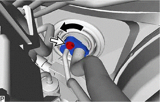
Rotate the hook connector as shown in the illustration.
-
Insert the pipe joint into the fitting hole securely and install the bolt.
- Torque:
- 9.8 N*m { 100 kgf*cm, 87 in.*lbf }
-
-
CONNECT INLET HEATER WATER HOSE
-
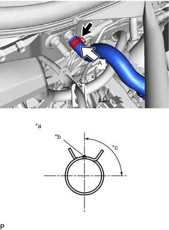
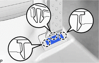
*a View A *b Marking (Green) *c Clip Installation Angle (75 to 105°) Connect the inlet heater water hose with the marking (green) facing up and engage the clip within the area shown in the illustration.
Note
Do not apply excessive force to the inlet heater water hose.
-
-
CONNECT OUTLET HEATER WATER HOSE
-
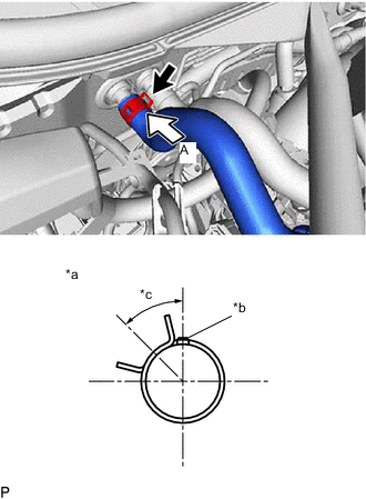
*a View A *b Marking (Green) *c Clip Installation Angle (30 to 60°) Connect the outlet heater water hose with the marking (green) facing up and engage the clip within the area shown in the illustration.
Note
Do not apply excessive force to the outlet heater water hose.
-
-
INSTALL WINDSHIELD WIPER MOTOR AND LINK ASSEMBLY
-
ADD ENGINE COOLANT
-
INSPECT FOR COOLANT LEAK
-
CHARGE AIR CONDITIONING SYSTEM WITH REFRIGERANT (for HFC-134a(R134a))
-
CHARGE AIR CONDITIONING SYSTEM WITH REFRIGERANT (for HFO-1234yf(R1234yf))
-
WARM UP ENGINE (for HFC-134a(R134a))
-
WARM UP ENGINE (for HFO-1234yf(R1234yf))
-
INSPECT FOR REFRIGERANT LEAK (for HFC-134a(R134a))
-
INSPECT FOR REFRIGERANT LEAK (for HFO-1234yf(R1234yf))
-
INITIALIZE SERVO MOTOR