| DTC Code | DTC Name |
|---|---|
| ECO Switch Circuit |
DESCRIPTION
When the combination switch assembly (ECO mode switch) is turned on, the air conditioning amplifier assembly receives a combination switch assembly (ECO mode switch) ON signal and controls the air conditioning to enhance fuel efficiency.
WIRING DIAGRAM
PROCEDURE
- Click here
READ VALUE USING GTS
-
Connect the GTS to the DLC3.
-
Turn the engine switch on (IG).
-
Turn the GTS on.
-
Enter the following menus: Body Electrical / Air Conditioner / Data List.
-
Read the Data List according to the display on the GTS.
- Body Electrical > Air Conditioner > Data List
Tester Display Measurement Item Range Normal Condition Diagnostic Note ECO Switch Combination switch assembly (ECO mode switch) OFF or ON ON: Combination switch assembly (ECO mode switch) being turned and held at ECO position
OFF: Combination switch assembly (ECO mode switch) not turned
- -
-
- Body Electrical > Air Conditioner > Data List
Tester Display ECO Switch -
-
-
-
OK Combination switch assembly (ECO mode switch) condition displayed on the GTS changes with the actual switch operation. Result Proceed to OK NG - Body Electrical > Air Conditioner > Data List
- OK
PROCEED TO NEXT SUSPECTED AREA SHOWN IN PROBLEM SYMPTOMS TABLEClick here
- NGClick here
-
- Click here
INSPECT COMBINATION SWITCH ASSEMBLY (ECO MODE SWITCH)
-
Remove the combination switch assembly (ECO mode switch).
-
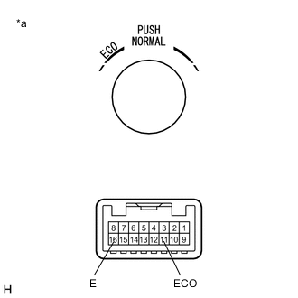
*a Component without harness connected
(Combination Switch Assembly (ECO Mode Switch))
Measure the resistance according to the value(s) in the table below.
Standard Resistance Tester Connection Condition Specified Condition 11 (ECO) - 16 (E) Combination switch assembly (ECO mode switch) not turned 10 kΩ or higher 11 (ECO) - 16 (E) Combination switch assembly (ECO mode switch) being turned and held at ECO position Below 50 Ω Result Proceed to OK NG
- OKClick here
- NG
REPLACE COMBINATION SWITCH ASSEMBLY (ECO MODE SWITCH)Click here
-
- Click here
CHECK HARNESS AND CONNECTOR (COMBINATION SWITCH ASSEMBLY (ECO MODE SWITCH) - AIR CONDITIONING AMPLIFIER ASSEMBLY)
-
Disconnect the O9 air conditioning amplifier assembly connector.
-
Measure the resistance according to the value(s) in the table below.
Standard Resistance Tester Connection Condition Specified Condition O9-29 (ECOS) - O78-11 (ECO) Always Below 1 Ω O9-29 (ECOS) - Body ground Always 10 kΩ or higher Result Proceed to OK NG
- OKClick here
- NG
REPAIR OR REPLACE HARNESS OR CONNECTOR
-
- Click here
CHECK HARNESS AND CONNECTOR (COMBINATION SWITCH ASSEMBLY (ECO MODE SWITCH) - BODY GROUND)
-
Measure the resistance according to the value(s) in the table below.
Standard Resistance Tester Connection Condition Specified Condition O78-16 (E) - Body ground Always Below 1 Ω Result Proceed to OK NG
- OK
REPLACE AIR CONDITIONING AMPLIFIER ASSEMBLYClick here
- NG
REPAIR OR REPLACE HARNESS OR CONNECTOR
-