AIR CONDITIONING SYSTEM, Diagnostic DTC:B1451/51
| DTC Code | DTC Name |
|---|---|
| B1451/51 | Compressor Solenoid Circuit |
DESCRIPTION
In this circuit, the compressor assembly with pulley (compressor solenoid) receives a refrigerant compression demand signal from the air conditioning amplifier assembly.
| DTC No. | Detection Item | DTC Detection Condition | Trouble Area | Memory |
|---|---|---|---|---|
| B1451/51 | Compressor Solenoid Circuit | Open or short in compressor solenoid circuit |
|
- |
WIRING DIAGRAM
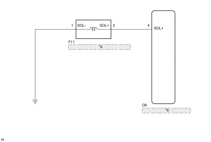
| *a | Compressor Assembly with Pulley (Compressor Solenoid) |
| *b | Air Conditioning Amplifier Assembly |
PROCEDURE
-
INSPECT COMPRESSOR ASSEMBLY WITH PULLEY (COMPRESSOR SOLENOID)
-
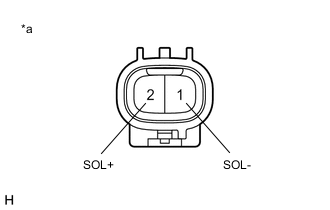
*a Component without harness connected
(Compressor Assembly with Pulley (Compressor Solenoid))
Disconnect the compressor assembly with pulley (compressor solenoid) connector.
-
Measure the resistance according to the value(s) in the table below.
Standard Resistance Tester Connection Condition Specified Condition 1 (SOL-) - 2 (SOL+) 25°C (77°F) 10.1 to 11.1 Ω Result Proceed to OK NG
NG 
REPLACE COMPRESSOR ASSEMBLY WITH PULLEY (COMPRESSOR SOLENOID) Click here
OK 
-
-
CHECK HARNESS AND CONNECTOR (COMPRESSOR ASSEMBLY WITH PULLEY (COMPRESSOR SOLENOID) - BODY GROUND)
-
Measure the resistance according to the value(s) in the table below.
Standard Resistance Tester Connection Condition Specified Condition F11-1 (SOL-) - Body ground Always Below 1 Ω Result Proceed to OK NG
NG
REPAIR OR REPLACE HARNESS OR CONNECTOR
OK
-
-
CHECK HARNESS AND CONNECTOR (COMPRESSOR ASSEMBLY WITH PULLEY (COMPRESSOR SOLENOID) - AIR CONDITIONING AMPLIFIER ASSEMBLY)
-
Disconnect the O9 air conditioning amplifier assembly connector.
-
Measure the resistance according to the value(s) in the table below.
Standard Resistance Tester Connection Condition Specified Condition F11-2 (SOL+) - O9-4 (SOL+) Always Below 1 Ω F11-2 (SOL+) - Body ground Always 10 kΩ or higher Result Result Proceed to NG A OK (When troubleshooting according to the Problem Symptoms Table) B OK (When troubleshooting according to the DTC) C
A
REPAIR OR REPLACE HARNESS OR CONNECTOR
B
PROCEED TO NEXT SUSPECTED AREA SHOWN IN PROBLEM SYMPTOMS TABLE Click here
C
REPLACE AIR CONDITIONING AMPLIFIER ASSEMBLY Click here
-