PROCEDURE
- Click here
INSPECT MAP LIGHT ASSEMBLY
-
Measure the resistance according to the value(s) in the table below.
Standard Resistance Tester Connection Condition Specified Condition W3-4 (+B1) - W4-14 (RIFR) Always Below 1 Ω W4-10 (RLMP) - W4-20 (GND9) Always Below 1 Ω If the result is not as specified, replace the map light assembly.
-
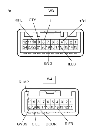
*a Component without harness connected
(Map Light Assembly)
Inspect the front map light.
-
Apply battery voltage to the connector and check that the front map light comes on.
OK Measurement Condition Condition Specified Condition Battery positive (+) → W3-4 (+B1)
Battery negative (-) → W4-20 (GND9)
Front map light switch LH on Front map light LH comes on Front map light switch RH on Front map light RH comes on If the result is not as specified, replace the bulb or map light assembly.
-
-
Inspect the front dome light.
-
Apply battery voltage to the connector and check that the front dome light comes on.
OK Measurement Condition Condition Specified Condition Battery positive (+) → W3-4 (+B1)
Battery negative (-) → W3-9 (CTY)
Always Front dome light comes on Battery positive (+) → W3-4 (+B1)
Battery negative (-) → W3-10 (RIFL)
If the result is not as specified, replace the bulb or map light assembly.
-
-
Inspect the door switch.
-
Measure the resistance according to the value(s) in the table below.
Standard Resistance Tester Connection Condition Specified Condition W4-18 (DOOR) - W4-20 (GND9) Door switch on Below 1 Ω W4-18 (DOOR) - W4-20 (GND9) Door switch off 10 kΩ or higher If the result is not as specified, replace the map light assembly.
-
-
Inspect the switch illumination.
-
Apply battery voltage to the connector and check that the switch illumination comes on.
OK Measurement Condition Condition Specified Condition Battery positive (+) → W3-16 (ILLB)
Battery negative (-) → W3-8 (LILL)
Always Switch illumination comes on If the result is not as specified, replace the map light assembly.
-
-
Inspect the intrusion sensor cancel switch. (w/ Intrusion Sensor Cancel Switch)
-
Measure the resistance according to the value(s) in the table below.
Standard Resistance Tester Connection Condition Specified Condition W3-22 (SOFF) - W3-19 (GND) Intrusion sensor cancel switch pushed and held Below 1 Ω W3-22 (SOFF) - W3-19 (GND) Intrusion sensor cancel switch not pushed 10 kΩ or higher If the result is not as specified, replace the map light assembly.
-
-