LIGHTING SYSTEM Remote Touchpad Illumination Light Circuit
DESCRIPTION
The main body ECU (multiplex network body ECU) detects the condition of the rear door courtesy light switch assembly.
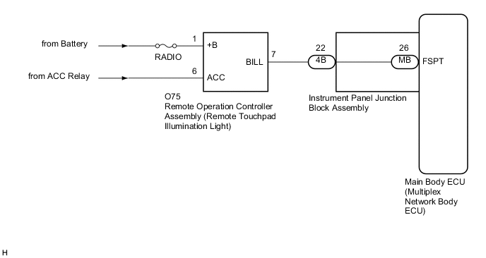
WIRING DIAGRAM
CAUTION / NOTICE / HINT
Note
Before replacing the main ECU (multiplex network body ECU), refer to Service Bulletin.
PROCEDURE
-
PERFORM ACTIVE TEST USING GTS
-
Connect the GTS to the DLC3.
-
Start the engine.
-
Turn the GTS on.
-
Enter the following menus: Body Electrical / (desired system) / Active Test.
-
Perform the Active Test according to the display on the GTS.
Body Electrical > Main Body > Active TestTester Display Measurement Item Control Range Diagnostic Note Interior Illumination Light2 Remote touchpad illumination lights ON or OFF Preconditions for using the Active Test to check dimmer controlled illumination:
-
Engine switch on.
-
Shift lever is in any position other than P.
Body Electrical > Main Body > Active TestTester Display Interior Illumination Light2 OK Remote touchpad illumination lights comes on. Result Proceed to OK NG -
OK 
PROCEED TO NEXT SUSPECTED AREA SHOWN IN PROBLEM SYMPTOMS TABLE Click here
NG 
-
-
CHECK HARNESS AND CONNECTOR (BATTERY - REMOTE OPERATION CONTROLLER ASSEMBLY)
-
Disconnect the O75 remote operation controller assembly connector.
-
Measure the voltage according to the value(s) in the table below.
Standard Voltage Tester Connection Condition Specified Condition O75-1 (+B) - Body ground Always 11 to 14 V O75-6 (ACC) - Body ground Engine switch on (ACC) or on (IG) 11 to 14 V Result Proceed to OK NG
NG
REPAIR OR REPLACE HARNESS OR CONNECTOR
OK
-
-
INSPECT REMOTE OPERATION CONTROLLER ASSEMBLY
-
Remove the remote operation controller assembly.
-
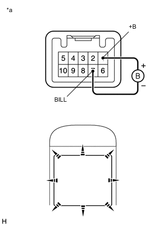
*a Component without harness connected
(Remote Operation Controller Assembly)
Apply battery voltage to the connector and check that the remote touchpad illumination light comes on.
Standard Measurement Condition Condition Specified Condition Battery positive (+) → O75-1 (+B)
Battery negative (-) → O75-7 (BILL)
Always Remote touchpad illumination light comes on Result Proceed to OK NG
NG
REPLACE REMOTE OPERATION CONTROLLER ASSEMBLY Click here
OK
-
-
CHECK HARNESS AND CONNECTOR (REMOTE OPERATION CONTROLLER ASSEMBLY - INSTRUMENT PANEL JUNCTION BLOCK ASSEMBLY)
-
Disconnect the 4B instrument panel junction block assembly connector.
-
Measure the resistance according to the value(s) in the table below.
Standard Resistance Tester Connection Condition Specified Condition O75-7(BILL) - 4B-22 Always Below 1 Ω O75-7(BILL) - Body ground Always 10 kΩ or higher Result Proceed to OK NG
NG
REPAIR OR REPLACE HARNESS OR CONNECTOR
OK
-
-
INSPECT INSTRUMENT PANEL JUNCTION BLOCK ASSEMBLY
-
Remove the instrument panel junction block assembly.
-
Remove the main body ECU (multiplex network body ECU) from the instrument panel junction block assembly.
-
Measure the resistance according to the value(s) in the table below.
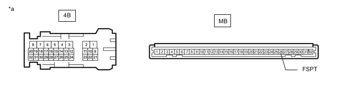
*a Component without harness connected
(Instrument Panel Junction Block Assembly)
- - Standard Resistance Tester Connection Condition Specified Condition 4B-22 - MB-26 (FSPT) Always Below 1 Ω Result Proceed to OK NG
OK
REPLACE MAIN BODY ECU (MULTIPLEX NETWORK BODY ECU) Click here
NG
REPLACE INSTRUMENT PANEL JUNCTION BLOCK ASSEMBLY Click here
-