| DTC Code | DTC Name |
|---|---|
| Theft Warning Siren Circuit |
DESCRIPTION
The theft warning siren assembly sounds if either of the following conditions is met:
-
The theft deterrent system is in the alarm sounding state.
-
The theft warning siren assembly is in the armed state when the power source, ground or communication line is open.
CAUTION / NOTICE / HINT
-
Before replacing the main body ECU (multiplex network body ECU), refer to Service Bulletin.
-
Inspect the fuses for circuits related to this system before performing the following procedure.
PROCEDURE
- Click here
PERFORM ACTIVE TEST USING GTS (SECURITY HORN2)
-
Connect the GTS to the DLC3.
-
Turn the engine switch on (IG).
-
Turn the GTS on.
-
Enter the following menus: Body Electrical / Main Body / Active Test.
-
Perform the Active Test according to the display on the GTS.
- Body Electrical > Main Body > Active Test
Tester Display Measurement Item Control Range Diagnostic Note Security Horn2 Theft warning siren assembly OFF/ON - -
-
- Body Electrical > Main Body > Active Test
Tester Display Security Horn2 -
-
-
-
OK The theft warning siren assembly sounds and stops correctly when operated using the GTS. Result Proceed to OK NG - Body Electrical > Main Body > Active Test
- OK
REPLACE MAIN BODY ECU (MULTIPLEX NETWORK BODY ECU)Click here
- NGClick here
-
- Click here
CHECK HARNESS AND CONNECTOR (BATTERY - THEFT WARNING SIREN ASSEMBLY - BODY GROUND)
-
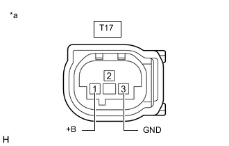
*a Front view of wire harness connector
(to Theft Warning Siren Assembly)
Disconnect the T48 theft warning siren assembly connector.
-
Measure the voltage and resistance according to the value(s) in the table below.
Standard Voltage Tester Connection Condition Specified Condition T48-1 (+B) - Body ground Always 11 to 14 V Standard Resistance Tester Connection Condition Specified Condition T48-3 (GND) - Body ground Always Below 1 Ω Result Proceed to OK NG
- OKClick here
- NG
REPAIR OR REPLACE HARNESS OR CONNECTOR
-
- Click here
CHECK HARNESS AND CONNECTOR (MAIN BODY ECU (MULTIPLEX NETWORK BODY ECU) - THEFT WARNING SIREN ASSEMBLY)
-
Disconnect the O1 main body ECU (multiplex network body ECU) connector.
-
Measure the resistance according to the value(s) in the table below.
Standard Resistance Tester Connection Condition Specified Condition O1-18 (SSCL) - T48-2 (CONT) Always Below 1 Ω O1-18 (SSCL) or T48-2 (CONT) - Body ground Always 10 kΩ or higher Result Proceed to OK NG
- OKClick here
- NG
REPAIR OR REPLACE HARNESS OR CONNECTOR
-
- Click here
REPLACE THEFT WARNING SIREN ASSEMBLY
-
Temporarily replace the theft warning siren assembly with a new or known good one.
Tip:Refer to Service Bulletin.
Result Proceed to NEXT
- NEXTClick here
-
- Click here
CHECK THEFT WARNING SIREN ASSEMBLY
-
Turn the engine switch on (IG), then off.
-
Set the theft deterrent system to "ARMED STATE".
-
Check that the security indicator changes from illuminated to blinking.
-
Change the theft deterrent system to "ALARM SOUNDING STATE".
-
Check that the theft warning siren assembly is sounding.
OK Theft warning siren assembly is sounding. Result Proceed to OK NG
- OK
END (THEFT WARNING SIREN ASSEMBLY WAS DEFECTIVE)
- NG
REPLACE MAIN BODY ECU (MULTIPLEX NETWORK BODY ECU)Click here
-