CAN COMMUNICATION SYSTEM Check Bus 5 Line for Short to GND
DESCRIPTION
There may be a short circuit between one of the CAN bus lines and GND when there is no resistance between terminal 15 (CA5H) of the central gateway ECU (network gateway ECU) and terminal 4 (CG) of the DLC3, or terminal 16 (CA5L) of the central gateway ECU (network gateway ECU) and terminal 4 (CG) of the DLC3.
| Symptom | Trouble Area |
|---|---|
| There is no resistance between terminal 15 (CA5H) of the central gateway ECU (network gateway ECU) and terminal 4 (CG) of the DLC3, or terminal 16 (CA5L) of the central gateway ECU (network gateway ECU) and terminal 4 (CG) of the DLC3. |
|
WIRING DIAGRAM
Figure 1. for LHD:
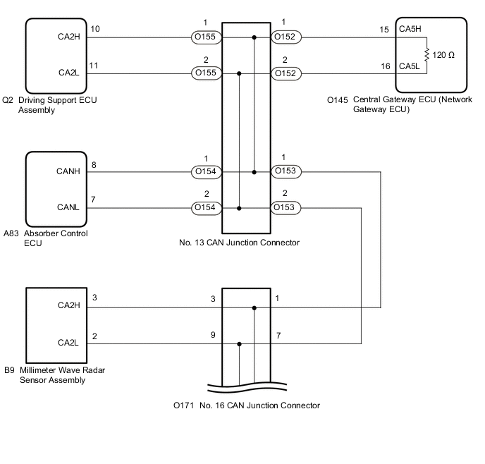
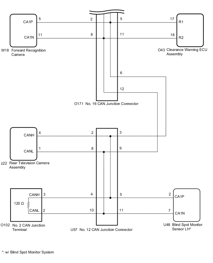
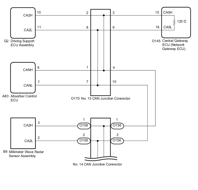
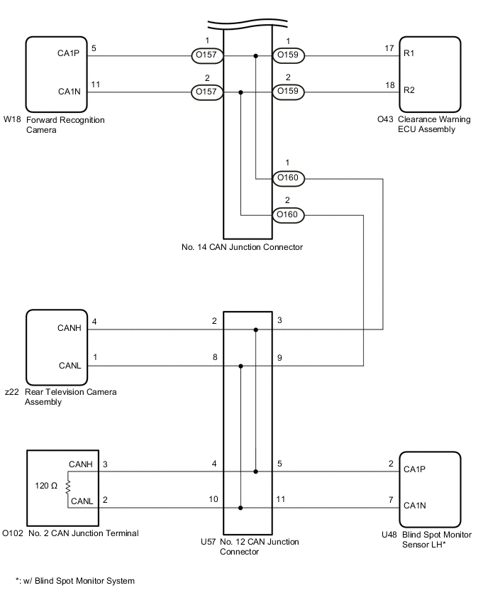
Figure 2. for RHD:
CAUTION / NOTICE / HINT
CAUTION:
When performing the confirmation driving pattern, obey all speed limits and traffic laws.
Note
-
Because the order of diagnosis is important to allow correct diagnosis, make sure to begin troubleshooting using How to Proceed with Troubleshooting when CAN communication system related DTCs are output.
-
Before measuring the resistance of the CAN bus, turn the engine switch off and leave the vehicle for 1 minute or more without operating the key or any switches, or opening or closing the doors. After that, disconnect the cable from the negative (-) battery terminal and leave the vehicle for 1 minute or more before measuring the resistance.
-
After turning the engine switch off, waiting time may be required before disconnecting the cable from the negative (-) battery terminal. Therefore, make sure to read the disconnecting the cable from the negative (-) battery terminal notices before proceeding with work.
-
After performing repairs, perform the DTC check procedure and confirm that the DTCs are not output again.
DTC check procedure: Turn the engine switch on (IG) and wait for 1 minute or more. Then operate the suspected malfunctioning system and drive the vehicle at 60 km/h (37 mph) or more for 5 minutes or more.
-
After the repair, perform the CAN bus check and check that all the ECUs and sensors connected to the CAN communication system are displayed as normal.
Tech Tips
-
Before disconnecting related connectors for inspection, push in on each connector body to check that the connector is not loose or disconnected.
-
When a connector is disconnected, check that the terminals and connector body are not cracked, deformed or corroded.
PROCEDURE
-
CHECK VEHICLE TYPE
-
Check vehicle type.
Result Result Proceed to for LHD A for RHD B
B 
CHECK FOR SHORT TO GND IN CAN BUS LINE (NO. 14 CAN JUNCTION CONNECTOR) Click here
A 
-
-
CHECK FOR SHORT TO GND IN CAN BUS LINE (NO. 16 CAN JUNCTION CONNECTOR)
-
Disconnect the cable from the negative (-) battery terminal.
-
Disconnect the O171 No. 16 CAN junction connector.
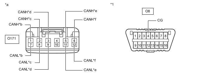
*1 DLC3 - - *a Front view of wire harness connector
(to No. 16 CAN Junction Connector)
*b to No. 13 CAN Junction Connector *c to Forward Recognition Camera *d to Millimeter Wave Radar Sensor Assembly *e to Clearance Warning ECU Assembly *f to No. 12 CAN Junction Connector -
Measure the resistance according to the value(s) in the table below.
Standard Resistance Tester Connection Condition Specified Condition Connected to O171-1 (CANH) - O8-4 (CG) Cable disconnected from negative (-) battery terminal 200 Ω or higher No. 13 CAN junction connector O171-7 (CANL) - O8-4 (CG) O171-2 (CANH) - O8-4 (CG) Cable disconnected from negative (-) battery terminal 200 Ω or higher Forward recognition camera O171-8 (CANL) - O8-4 (CG) O171-3 (CANH) - O8-4 (CG) Cable disconnected from negative (-) battery terminal 200 Ω or higher Millimeter wave radar sensor assembly O171-9 (CANL) - O8-4 (CG) O171-5 (CANH) - O8-4 (CG) Cable disconnected from negative (-) battery terminal 200 Ω or higher Clearance warning ECU assembly O171-11 (CANL) - O8-4 (CG) O171-6 (CANH) - O8-4 (CG) Cable disconnected from negative (-) battery terminal 200 Ω or higher No. 12 CAN junction connector O171-12 (CANL) - O8-4 (CG) Result Result Proceed to OK A NG (Line to No. 13 CAN junction connector) B NG (Line to No. 12 CAN junction connector) C NG (Line to ECU or sensor) D
A 
REPLACE NO. 16 CAN JUNCTION CONNECTOR
C
CHECK FOR SHORT TO GND IN CAN BUS LINE (NO. 12 CAN JUNCTION CONNECTOR) Click here
D
GO TO STEP 12 Click here
B
-
-
CHECK FOR SHORT TO GND IN CAN BUS LINE (NO. 13 CAN JUNCTION CONNECTOR)
-
Reconnect the O171 No. 16 CAN junction connector.
-
Disconnect the O152, O153, O154 and O155 No. 13 CAN junction connectors.
Tech Tips
Connectors that connect to the CAN junction connector can be distinguished by the color of their CAN bus lines. When the connectors have been disconnected from the CAN junction connector, reconnecting the connectors to non-original positions on the CAN junction connector does not affect system performance. However, it is preferred to reconnect the connectors to their original positions to avoid negative effects on the wiring such as tension on the wire harnesses, and to make future maintenance easier.
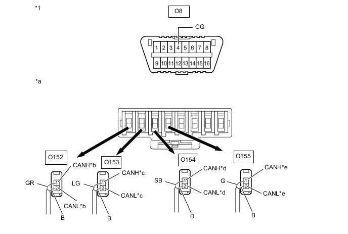
*1 DLC3 - - *a Rear view of wire harness connector
(to No. 13 CAN Junction Connector)
*b to Central Gateway ECU (Network Gateway ECU) *c to No. 16 CAN Junction Connector *d to Absorber Control ECU *e to Driving Support ECU Assembly - - Wiring Color: Code Color (CANH Side) Color (CANL Side) Connected to O152 GR B Central gateway ECU (network gateway ECU) O153 LG B No. 16 CAN junction connector O154 SB B Absorber control ECU O155 G B Driving support ECU assembly -
Measure the resistance according to the value(s) in the table below.
Standard Resistance Tester Connection Condition Specified Condition Connected to O152-1 (CANH) - O8-4 (CG) Cable disconnected from negative (-) battery terminal 200 Ω or higher Central gateway ECU (network gateway ECU) O152-2 (CANL) - O8-4 (CG) O153-1 (CANH) - O8-4 (CG) Cable disconnected from negative (-) battery terminal 200 Ω or higher No. 16 CAN junction connector O153-2 (CANL) - O8-4 (CG) O154-1 (CANH) - O8-4 (CG) Cable disconnected from negative (-) battery terminal 200 Ω or higher Absorber control ECU O154-2 (CANL) - O8-4 (CG) O155-1 (CANH) - O8-4 (CG) Cable disconnected from negative (-) battery terminal 200 Ω or higher Driving support ECU assembly O155-2 (CANL) - O8-4 (CG) Result Result Proceed to OK A NG (Line to central gateway ECU (network gateway ECU)) B NG (Line to No. 16 CAN junction connector) C NG (Line to ECU or sensor) D
A
REPLACE NO. 13 CAN JUNCTION CONNECTOR
C
REPAIR OR REPLACE CAN MAIN BUS LINE OR CONNECTOR (NO. 13 CAN JUNCTION CONNECTOR - NO. 16 CAN JUNCTION CONNECTOR)
D
GO TO STEP 12 Click here
B
-
-
CHECK FOR SHORT TO GND IN CAN BUS LINE (CENTRAL GATEWAY ECU (NETWORK GATEWAY ECU))
-
Reconnect the O152, O153, O154 and O155 No. 13 CAN junction connectors.
-
Disconnect the O145 central gateway ECU (network gateway ECU) connector.
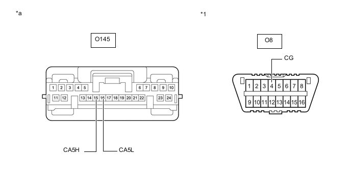
*1 DLC3 - - *a Front view of wire harness connector
(to Central Gateway ECU (Network Gateway ECU))
- - -
Measure the resistance according to the value(s) in the table below.
Standard Resistance Tester Connection Condition Specified Condition O145-15 (CA5H) - O8-4 (CG) Cable disconnected from negative (-) battery terminal 200 Ω or higher O145-16 (CA5L) - O8-4 (CG) Result Result OK NG
OK
REPLACE CENTRAL GATEWAY ECU (NETWORK GATEWAY ECU) Click here
NG
REPAIR OR REPLACE CAN MAIN BUS LINE OR CONNECTOR (CENTRAL GATEWAY ECU (NETWORK GATEWAY ECU) - NO. 13 CAN JUNCTION CONNECTOR)
-
-
CHECK FOR SHORT TO GND IN CAN BUS LINE (NO. 12 CAN JUNCTION CONNECTOR)
-
Reconnect the O171 No. 16 CAN junction connector.
-
Disconnect the U57 No. 12 CAN junction connector.
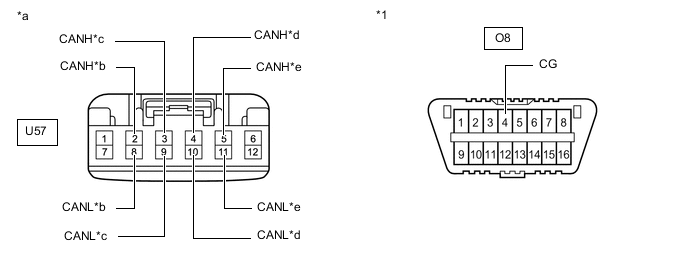
*1 DLC3 - - *a Front view of wire harness connector
(to No. 12 CAN Junction Connector)
*b to Rear Television Camera Assembly *c to No. 16 CAN Junction Connector *d to No. 2 CAN Junction Terminal *e to Blind Spot Monitor Sensor LH
(w/ Blind Spot Monitor System)
- - -
Measure the resistance according to the value(s) in the table below.
Standard Resistance Tester Connection Condition Specified Condition Connected to U57-2 (CANH) - O8-4 (CG) Cable disconnected from negative (-) battery terminal 200 Ω or higher Rear television camera assembly U57-8 (CANL) - O8-4 (CG) U57-3 (CANH) - O8-4 (CG) Cable disconnected from negative (-) battery terminal 200 Ω or higher No. 16 CAN junction connector U57-9 (CANL) - O8-4 (CG) U57-4 (CANH) - O8-4 (CG) Cable disconnected from negative (-) battery terminal 200 Ω or higher No. 2 CAN junction terminal U57-10 (CANL) - O8-4 (CG) U57-5 (CANH) - O8-4 (CG) Cable disconnected from negative (-) battery terminal 200 Ω or higher Blind spot monitor sensor LH* U57-11 (CANL) - O8-4 (CG)
-
*: w/ Blind Spot Monitor System
Result Result Proceed to OK A NG (Line to No. 16 CAN junction connector) B NG (Line to No. 2 CAN junction terminal) C NG (Line to ECU or sensor) D -
A
REPLACE NO. 12 CAN JUNCTION CONNECTOR
B
REPAIR OR REPLACE CAN MAIN BUS LINE OR CONNECTOR (NO. 12 CAN JUNCTION CONNECTOR - NO. 16 CAN JUNCTION CONNECTOR)
D
GO TO STEP 12 Click here
C
-
-
CHECK FOR SHORT TO GND IN CAN BUS LINE (NO. 2 CAN JUNCTION TERMINAL)
-
Reconnect the U57 No. 12 CAN junction connector.
-
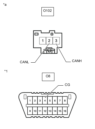
*1 DLC3 *a Front view of wire harness connector
(to No. 2 CAN Junction Terminal)
Disconnect the O102 No. 2 CAN junction terminal connector.
-
Measure the resistance according to the value(s) in the table below.
Standard Resistance Tester Connection Condition Specified Condition O102-3 (CANH) - O8-4 (CG) Cable disconnected from negative (-) battery terminal 200 Ω or higher O102-2 (CANL) - O8-4 (CG) Result Result OK NG
OK
REPLACE NO. 2 CAN JUNCTION TERMINAL
NG
REPAIR OR REPLACE CAN MAIN BUS LINE OR CONNECTOR (NO. 2 CAN JUNCTION TERMINAL - NO. 12 CAN JUNCTION CONNECTOR)
-
-
CHECK FOR SHORT TO GND IN CAN BUS LINE (NO. 14 CAN JUNCTION CONNECTOR)
-
Disconnect the cable from the negative (-) battery terminal.
-
Disconnect the O156, O157, O158, O159 and O160 No. 14 CAN junction connectors.
Tech Tips
Connectors that connect to the CAN junction connector can be distinguished by the color of their CAN bus lines. When the connectors have been disconnected from the CAN junction connector, reconnecting the connectors to non-original positions on the CAN junction connector does not affect system performance. However, it is preferred to reconnect the connectors to their original positions to avoid negative effects on the wiring such as tension on the wire harnesses, and to make future maintenance easier.
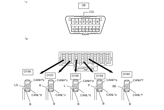
*1 DLC3 - - *a Rear view of wire harness connector
(to No. 14 CAN Junction Connector)
*b to No. 15 CAN Junction Connector *c to Forward Recognition Camera *d to Millimeter Wave Radar Sensor Assembly *e to Clearance Warning ECU Assembly *f to No. 12 CAN Junction Connector Wiring Color: Code Color (CANH Side) Color (CANL Side) Connected to O156 LG B No. 15 CAN junction connector O157 R B Forward recognition camera O158 L B Millimeter wave radar sensor assembly O159 P B Clearance warning ECU assembly O160 BE B No. 12 CAN junction connector -
Measure the resistance according to the value(s) in the table below.
Standard Resistance Tester Connection Condition Specified Condition Connected to O156-1 (CANH) - O8-4 (CG) Cable disconnected from negative (-) battery terminal 200 Ω or higher No. 15 CAN junction connector O156-2 (CANL) - O8-4 (CG) O157-1 (CANH) - O8-4 (CG) Cable disconnected from negative (-) battery terminal 200 Ω or higher Forward recognition camera O157-2 (CANL) - O8-4 (CG) O158-1 (CANH) - O8-4 (CG) Cable disconnected from negative (-) battery terminal 200 Ω or higher Millimeter wave radar sensor assembly O158-2 (CANL) - O8-4 (CG) O159-1 (CANH) - O8-4 (CG) Cable disconnected from negative (-) battery terminal 200 Ω or higher Clearance warning ECU assembly O159-2 (CANL) - O8-4 (CG) O160-1 (CANH) - O8-4 (CG) Cable disconnected from negative (-) battery terminal 200 Ω or higher No. 12 CAN junction connector O160-2 (CANL) - O8-4 (CG) Result Result Proceed to OK A NG (Line to No. 15 CAN junction connector) B NG (Line to No. 12 CAN junction connector) C NG (Line to ECU or sensor) D
A
REPLACE NO. 14 CAN JUNCTION CONNECTOR
C
CHECK FOR SHORT TO GND IN CAN BUS LINE (NO. 12 CAN JUNCTION CONNECTOR) Click here
D
CHECK FOR SHORT TO GND IN CAN BUS LINE (ECU OR SENSOR) Click here
B
-
-
CHECK FOR SHORT TO GND IN CAN BUS LINE (NO. 15 CAN JUNCTION CONNECTOR)
-
Reconnect the O156, O157, O158, O159 and O160 No. 14 CAN junction connectors.
-
Disconnect the O170 No. 15 CAN junction connector.
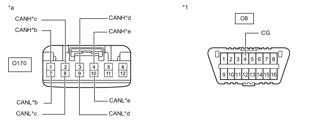
*1 DLC3 - - *a Front view of wire harness connector
(to No. 15 CAN Junction Connector)
*b to Absorber Control ECU *c to Driving Support ECU Assembly *d to Central Gateway ECU (Network Gateway ECU) *e to No. 14 CAN Junction Connector - - -
Measure the resistance according to the value(s) in the table below.
Standard Resistance Tester Connection Condition Specified Condition Connected to O170-1 (CANH) - O8-4 (CG) Cable disconnected from negative (-) battery terminal 200 Ω or higher Absorber control ECU O170-7 (CANL) - O8-4 (CG) O170-2 (CANH) - O8-4 (CG) Cable disconnected from negative (-) battery terminal 200 Ω or higher Driving support ECU assembly O170-8 (CANL) - O8-4 (CG) O170-3 (CANH) - O8-4 (CG) Cable disconnected from negative (-) battery terminal 200 Ω or higher Central gateway ECU (network gateway ECU) O170-9 (CANL) - O8-4 (CG) O170-4 (CANH) - O8-4 (CG) Cable disconnected from negative (-) battery terminal 200 Ω or higher No. 14 CAN junction connector O170-10 (CANL) - O8-4 (CG) Result Result Proceed to OK A NG (Line to central gateway ECU (network gateway ECU)) B NG (Line to No. 14 CAN junction connector) C NG (Line to ECU or sensor) D
A
REPLACE NO. 15 CAN JUNCTION CONNECTOR
C
REPAIR OR REPLACE CAN MAIN BUS LINE OR CONNECTOR (NO. 14 CAN JUNCTION CONNECTOR - NO. 15 CAN JUNCTION CONNECTOR)
D
GO TO STEP 12 Click here
B
-
-
CHECK FOR SHORT TO GND IN CAN BUS LINE (CENTRAL GATEWAY ECU (NETWORK GATEWAY ECU))
-
Reconnect the O170 No. 15 CAN junction connector.
-
Disconnect the O145 central gateway ECU (network gateway ECU) connector.
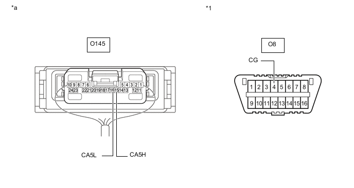
*1 DLC3 - - *a Front view of wire harness connector
(to Central Gateway ECU (Network Gateway ECU))
- - -
Measure the resistance according to the value(s) in the table below.
Standard Resistance Tester Connection Condition Specified Condition O145-15 (CA5H) - O8-4 (CG) Cable disconnected from negative (-) battery terminal 200 Ω or higher O145-16 (CA5L) - O8-4 (CG) Result Result OK NG
OK
REPLACE CENTRAL GATEWAY ECU (NETWORK GATEWAY ECU) Click here
NG
REPAIR OR REPLACE CAN MAIN BUS LINE OR CONNECTOR (CENTRAL GATEWAY ECU (NETWORK GATEWAY ECU) - NO. 15 CAN JUNCTION CONNECTOR)
-
-
CHECK FOR SHORT TO GND IN CAN BUS LINE (NO. 12 CAN JUNCTION CONNECTOR)
-
Reconnect the O156, O157, O158, O159 and O160 No. 14 CAN junction connectors.
-
Disconnect the U57 No. 12 CAN junction connector.
*1 DLC3 - - *a Front view of wire harness connector
(to No. 12 CAN Junction Connector)
*b to Rear Television Camera Assembly *c to No. 14 CAN Junction Connector *d to No. 2 CAN Junction Terminal *e to Blind Spot Monitor Sensor LH
(w/ Blind Spot Monitor System)
- - -
Measure the resistance according to the value(s) in the table below.
Standard Resistance Tester Connection Condition Specified Condition Connected to U57-2 (CANH) - O8-4 (CG) Cable disconnected from negative (-) battery terminal 200 Ω or higher Rear television camera assembly U57-8 (CANL) - O8-4 (CG) U57-3 (CANH) - O8-4 (CG) Cable disconnected from negative (-) battery terminal 200 Ω or higher No. 14 CAN junction connector U57-9 (CANL) - O8-4 (CG) U57-4 (CANH) - O8-4 (CG) Cable disconnected from negative (-) battery terminal 200 Ω or higher No. 2 CAN junction terminal U57-10 (CANL) - O8-4 (CG) U57-5 (CANH) - O8-4 (CG) Cable disconnected from negative (-) battery terminal 200 Ω or higher Blind spot monitor sensor LH* U57-11 (CANL) - O8-4 (CG)
-
*: w/ Blind Spot Monitor System
Result Result Proceed to OK A NG (Line to No. 14 CAN junction connector) B NG (Line to No. 2 CAN junction terminal) C NG (Line to ECU or sensor) D -
A
REPLACE NO. 12 CAN JUNCTION CONNECTOR
B
REPAIR OR REPLACE CAN MAIN BUS LINE OR CONNECTOR (NO. 12 CAN JUNCTION CONNECTOR - NO. 14 CAN JUNCTION CONNECTOR)
D
GO TO STEP 12 Click here
C
-
-
CHECK FOR SHORT TO GND IN CAN BUS LINE (NO. 2 CAN JUNCTION TERMINAL)
-
Reconnect the U57 No. 12 CAN junction connector.
-
*1 DLC3 *a Front view of wire harness connector
(to No. 2 CAN Junction Terminal)
Disconnect the O102 No. 2 CAN junction terminal connector.
-
Measure the resistance according to the value(s) in the table below.
Standard Resistance Tester Connection Condition Specified Condition O102-3 (CANH) - O8-4 (CG) Cable disconnected from negative (-) battery terminal 200 Ω or higher O102-2 (CANL) - O8-4 (CG) Result Result OK NG
OK
REPLACE NO. 2 CAN JUNCTION TERMINAL
NG
REPAIR OR REPLACE CAN MAIN BUS LINE OR CONNECTOR (NO. 2 CAN JUNCTION TERMINAL - NO. 12 CAN JUNCTION CONNECTOR)
-
-
CHECK FOR SHORT TO GND IN CAN BUS LINE (ECU OR SENSOR)
-
Reconnect all wire harness connectors.
-
Disconnect the connector that includes terminals CANH and CANL from the ECU or sensor to which the bus line shorted to GND is connected.
-
Measure the resistance according to the value(s) in the table below.
*1 DLC3 - - *a Component with harness connected
(Central Gateway ECU (Network Gateway ECU))
- - Standard Resistance Tester Connection Condition Specified Condition O145-15 (CA5H) - O8-4 (CG) Cable disconnected from negative (-) battery terminal 200 Ω or higher O145-16 (CA5L) - O8-4 (CG) Tech Tips
If the resistance changes to 200 Ω or higher when the connector is disconnected from the ECU or sensor, there may be a short in the ECU or sensor.
Result Result OK NG
OK
REPLACE ECU OR SENSOR
NG
REPAIR OR REPLACE ECU OR SENSOR BRANCH LINES OR CONNECTOR
-