| DTC Code | DTC Name |
|---|---|
| Center Airbag Sensor Communication Stop Mode |
DESCRIPTION
| Detection Item | Symptom | Trouble Area |
|---|---|---|
| Center Airbag Sensor Communication Stop Mode | Either condition is met:
|
|
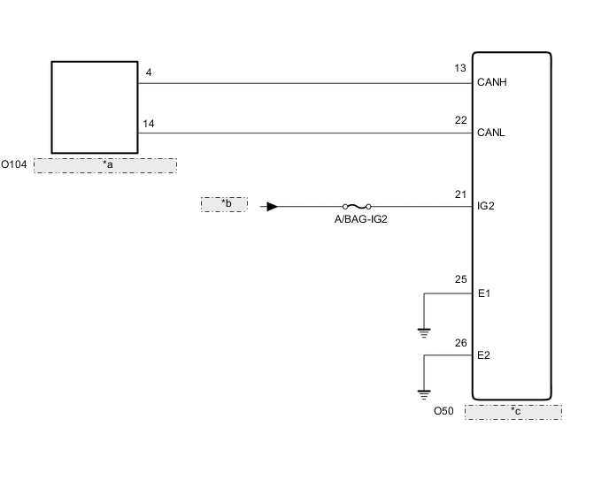
| *a | No. 1 CAN Junction Connector |
| *b | IG2 Relay |
| *c | Airbag ECU Assembly |
WIRING DIAGRAM
CAUTION / NOTICE / HINT
When performing the confirmation driving pattern, obey all speed limits and traffic laws.
-
Because the order of diagnosis is important to allow correct diagnosis, make sure to begin troubleshooting using How to Proceed with Troubleshooting when CAN communication system related DTCs are output.
-
Before measuring the resistance of the CAN bus, turn the engine switch off and leave the vehicle for 1 minute or more without operating the key or any switches, or opening or closing the doors. After that, disconnect the cable from the negative (-) battery terminal and leave the vehicle for 1 minute or more before measuring the resistance.
-
After turning the engine switch off, waiting time may be required before disconnecting the cable from the negative (-) battery terminal. Therefore, make sure to read the disconnecting the cable from the negative (-) battery terminal notices before proceeding with work.
-
After performing repairs, perform the DTC check procedure and confirm that the DTCs are not output again.
DTC check procedure: Turn the engine switch on (IG) and wait for 1 minute or more. Then operate the suspected malfunctioning system and drive the vehicle at 60 km/h (37 mph) or more for 5 minutes or more.
-
After the repair, perform the CAN bus check and check that all the ECUs and sensors connected to the CAN communication system are displayed.
-
Inspect the fuses for circuits related to this system before performing the following procedure.
-
Before disconnecting related connectors for inspection, push in on each connector body to check that the connector is not loose or disconnected.
-
When a connector is disconnected, check that the terminals and connector body are not cracked, deformed or corroded.
PROCEDURE
- Click here
CHECK FOR OPEN IN CAN BUS LINES (AIRBAG ECU ASSEMBLY BRANCH LINE)
-
Disconnect the cable from the negative (-) battery terminal.
-
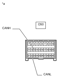
*a Front view of wire harness connector
(to Airbag ECU Assembly)
Disconnect the O50 airbag ECU assembly connector.
-
Measure the resistance according to the value(s) in the table below.
Standard Resistance Tester Connection Condition Specified Condition O50-13 (CANH) - O50-22 (CANL) Cable disconnected from negative (-) battery terminal 54 to 69 Ω Result Result OK NG
- OKClick here
- NG
REPAIR OR REPLACE CAN BRANCH LINES OR CONNECTOR (AIRBAG ECU ASSEMBLY)
-
- Click here
CHECK HARNESS AND CONNECTOR (POWER SOURCE CIRCUIT)
-
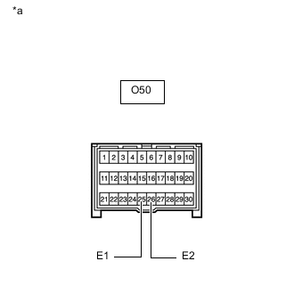
*a Front view of wire harness connector
(to Airbag ECU Assembly)
Measure the resistance according to the value(s) in the table below.
Standard Resistance Tester Connection Condition Specified Condition O50-25 (E1) - Body ground Cable disconnected from negative (-) battery terminal Below 1 Ω O50-26 (E2) - Body ground Cable disconnected from negative (-) battery terminal Below 1 Ω -
Reconnect the cable to the negative (-) battery terminal.
-
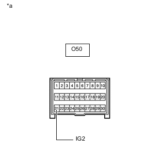
*a Front view of wire harness connector
(to Airbag ECU Assembly)
Measure the voltage according to the value(s) in the table below.
Standard Voltage Tester Connection Condition Specified Condition O50-21 (IG2) - Body ground Engine switch on (IG) 11 to 14 V Result Result OK NG
- OK
REPLACE AIRBAG ECU ASSEMBLYClick here
- NG
REPAIR OR REPLACE HARNESS OR CONNECTOR (POWER SOURCE CIRCUIT)
-