| DTC Code | DTC Name |
|---|---|
| U110F | Lost Communication With Roll Rate Sensor/Vertical Acceleration Sensor Module |
| U1172 | Lost Communication with Vehicle Dynamics Control Module (ch2) |
DESCRIPTION
| DTC No. | Detection Item | DTC Detection Condition | Trouble Area | Note |
|---|---|---|---|---|
| U110F | Lost Communication With Roll Rate Sensor/Vertical Acceleration Sensor Module | No communication from the roll rate and vertical acceleration sensor continues. |
|
Tip:
As there is no sub bus monitor ECU for V3 bus, each ECU detects communication stops and stores DTCs. |
| U1172 | Lost Communication with Vehicle Dynamics Control Module (ch2) | No communication from the skid control ECU (brake actuator assembly) continues. |
|
Tip:
As there is no sub bus monitor ECU for V3 bus, each ECU detects communication stops and stores DTCs. |
This diagnostic procedure is for when the torque vectoring differential ECU assembly (TVD) outputs only DTC U1172, the skid control ECU (brake actuator assembly) (ABS/VSC/TRAC) outputs only DTC U110F, or DTC U1172 and U110F are output simultaneously.
CAUTION / NOTICE / HINT
When performing the confirmation driving pattern, obey all speed limits and traffic laws.
-
Because the order of diagnosis is important to allow correct diagnosis, make sure to begin troubleshooting using How to Proceed with Troubleshooting when CAN communication system related DTCs are output.
-
Before measuring the resistance of the CAN bus, turn the engine switch off and leave the vehicle for 1 minute or more without operating the key or any switches, or opening or closing the doors. After that, disconnect the cable from the negative (-) battery terminal and leave the vehicle for 1 minute or more before measuring the resistance.
-
After turning the engine switch off, waiting time may be required before disconnecting the cable from the negative (-) battery terminal. Therefore, make sure to read the disconnecting the cable from the negative (-) battery terminal notices before proceeding with work.
-
After performing repairs, perform the DTC check procedure and confirm that the DTCs are not output again.
DTC check procedure: Turn the engine switch on (IG) and wait for 1 minute or more. Then operate the suspected malfunctioning system and drive the vehicle at 60 km/h (37 mph) or more for 5 minutes or more.
-
After the repair, perform the CAN bus check and check that all the ECUs and sensors connected to the CAN communication system are displayed as normal.
-
Before disconnecting related connectors for inspection, push in on each connector body to check that the connector is not loose or disconnected.
-
When a connector is disconnected, check that the terminals and connector body are not cracked, deformed or corroded.
PROCEDURE
- Click here
CHECK VEHICLE TYPE
-
Check vehicle type.
Result Result Proceed to for LHD A for RHD B
-
- Click here
CHECK VEHICLE TYPE
-
Check vehicle type.
Result Result Proceed to w/o Torque Vectoring Differential System A w/ Torque Vectoring Differential System B
-
- Click here
CHECK V3 BUS
-
Disconnect the cable from the negative (-) battery terminal.
-

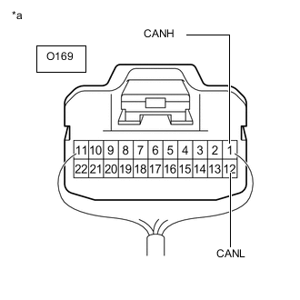
*1 DLC3 - - *a Component with harness connected
(No. 10 CAN Junction Connector)
- - Measure the resistance according to the value(s) in the table below.
Standard Resistance Tester Connection Condition Specified Condition Result O169-1 (CANH) - O169-12 (CANL) Cable disconnected from negative (-) battery terminal 54 to 69 Ω Below 54 Ω: Short circuit between bus lines 70 Ω or higher: Open circuit in main bus lines O169-1 (CANH) - O8-4 (CG) Cable disconnected from negative (-) battery terminal 200 Ω or higher Below 200 Ω: CANH short to ground O169-12 (CANL) - O8-4 (CG) Cable disconnected from negative (-) battery terminal 200 Ω or higher Below 200 Ω: CANL short to ground O169-1 (CANH) - O8-16 (BAT) Cable disconnected from negative (-) battery terminal 6 kΩ or higher Below 6 kΩ: CANH +B short O169-12 (CANL) - O8-16 (BAT) Cable disconnected from negative (-) battery terminal 6 kΩ or higher Below 6 kΩ: CANL +B short Result Result Proceed to OK A Open circuit in CAN main bus lines B Short circuit between bus lines C
-
Short to ground
-
+B short
D -
-
- Click here
CHECK FOR OPEN IN CAN BUS LINES (ROLL RATE AND VERTICAL ACCELERATION SENSOR BRANCH LINE)
-
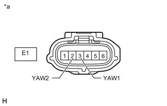
*a Front view of wire harness connector
(to Roll Rate and Vertical Acceleration Sensor)
Disconnect the E1 yaw rate sensor connector.
-
Measure the resistance according to the value(s) in the table below.
Standard Resistance Tester Connection Condition Specified Condition E1-3 (YAW1) - E1-2 (YAW2) Cable disconnected from negative (-) battery terminal 54 to 69 Ω Result Result OK NG
- OK
REPLACE ROLL RATE AND VERTICAL ACCELERATION SENSORClick here
- NG
REPAIR OR REPLACE CAN BRANCH LINES OR CONNECTOR (ROLL RATE AND VERTICAL ACCELERATION SENSOR)
-
- Click here
CHECK FOR OPEN IN V3 BUS MAIN LINES (NO. 10 CAN JUNCTION CONNECTOR)
-
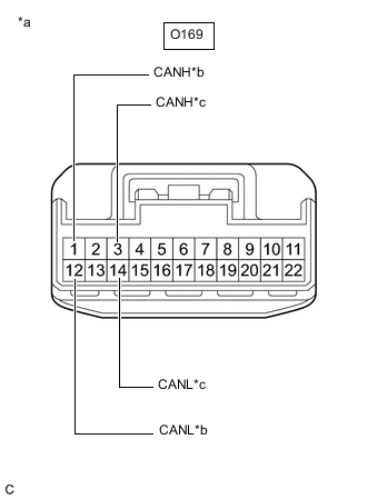
*a Front view of wire harness connector
(to No. 10 CAN Junction Connector)
*b to No. 8 CAN Junction Connector *c to ECM Disconnect the O169 No. 10 CAN junction connector.
-
Measure the resistance according to the value(s) in the table below.
Standard Resistance Tester Connection Condition Specified Condition Connected to O169-1 (CANH) - O169-12 (CANL) Cable disconnected from negative (-) battery terminal 108 to 132 Ω No. 8 CAN junction connector O169-3 (CANH) - O169-14 (CANL) Cable disconnected from negative (-) battery terminal 108 to 132 Ω ECM Result Result Proceed to OK A NG (ECM main lines) B NG (No. 8 CAN junction connector main lines) C
- A
REPLACE NO. 10 CAN JUNCTION CONNECTOR
- BClick here
- CClick here
-
- Click here
CHECK FOR OPEN IN V3 BUS MAIN LINES (ECM)
-
Reconnect the O169 No. 10 CAN junction connector.
-
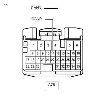
*a Front view of wire harness connector
(to ECM)
Disconnect the A78 ECM connector.
-
Measure the resistance according to the value(s) in the table below.
Standard Resistance Tester Connection Condition Specified Condition A78-11 (CANP) - A78-12 (CANN) Cable disconnected from negative (-) battery terminal 108 to 132 Ω Result Result OK NG
- OK
REPLACE ECMClick here
- NG
REPAIR OR REPLACE CAN MAIN BUS LINES OR CONNECTOR (ECM - NO. 10 CAN JUNCTION CONNECTOR)
-
- Click here
CHECK FOR OPEN IN V3 BUS MAIN LINES (NO. 8 CAN JUNCTION CONNECTOR)
-
Reconnect the O169 No. 10 CAN junction connector.
-
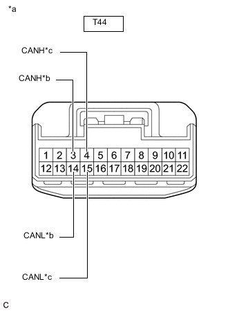
*a Front view of wire harness connector
(to No. 8 CAN Junction Connector)
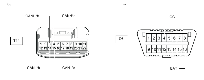
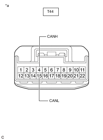
*b to Skid Control ECU (Brake Actuator Assembly) *c to No. 10 CAN Junction Connector Disconnect the T44 No. 8 CAN junction connector.
-
Measure the resistance according to the value(s) in the table below.
Standard Resistance Tester Connection Condition Specified Condition Connected to T44-3 (CANH) - T44-14 (CANL) Cable disconnected from negative (-) battery terminal 108 to 132 Ω Skid control ECU (brake actuator assembly) T44-4 (CANH) - T44-15 (CANL) Cable disconnected from negative (-) battery terminal 108 to 132 Ω No. 10 CAN junction connector Result Result Proceed to OK A NG (No. 10 CAN junction connector main lines) B NG (Skid control ECU (brake actuator assembly) main lines) C
- A
REPLACE NO. 8 CAN JUNCTION CONNECTOR
- B
REPAIR OR REPLACE CAN MAIN BUS LINES OR CONNECTOR (NO. 8 CAN JUNCTION CONNECTOR - NO. 10 CAN JUNCTION CONNECTOR)
- CClick here
-
- Click here
CHECK FOR OPEN IN V3 BUS MAIN LINES (SKID CONTROL ECU (BRAKE ACTUATOR ASSEMBLY))
-
Reconnect the T44 No. 8 CAN junction connector.
-
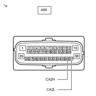
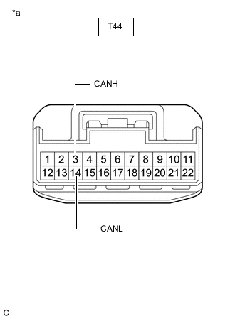
*a Front view of wire harness connector
(to Skid Control ECU (Brake Actuator Assembly))
Disconnect the A86 skid control ECU (brake actuator assembly) connector.
-
Measure the resistance according to the value(s) in the table below.
Standard Resistance Tester Connection Condition Specified Condition A86-36 (CA2H) - A86-37 (CA2L) Cable disconnected from negative (-) battery terminal 108 to 132 Ω Result Result OK NG
- OK
REPLACE SKID CONTROL ECU (BRAKE ACTUATOR ASSEMBLY)Click here
- NG
REPAIR OR REPLACE CAN MAIN BUS LINES OR CONNECTOR (SKID CONTROL ECU (BRAKE ACTUATOR ASSEMBLY) - NO. 8 CAN JUNCTION CONNECTOR)
-
- Click here
CHECK FOR SHORT IN V3 BUS LINES (SKID CONTROL ECU (BRAKE ACTUATOR ASSEMBLY))
-
*a Front view of wire harness connector
(to Skid Control ECU (Brake Actuator Assembly))
Disconnect the A86 skid control ECU (brake actuator assembly) connector.
-
Measure the resistance according to the value(s) in the table below.
Standard Resistance Tester Connection Condition Specified Condition A86-36 (CA2H) - A86-37 (CA2L) Cable disconnected from negative (-) battery terminal 108 to 132 Ω Result Result OK NG
- OK
REPLACE SKID CONTROL ECU (BRAKE ACTUATOR ASSEMBLY)Click here
- NGClick here
-
- Click here
CHECK FOR SHORT IN V3 BUS LINES (ECM)
-
Reconnect the A86 skid control ECU (brake actuator assembly) connector.
-
*a Front view of wire harness connector
(to ECM)
Disconnect the A78 ECM connector.
-
Measure the resistance according to the value(s) in the table below.
Standard Resistance Tester Connection Condition Specified Condition A78-11 (CANP) - A78-12 (CANN) Cable disconnected from negative (-) battery terminal 108 to 132 Ω Result Result OK NG
- OK
REPLACE ECMClick here
- NGClick here
-
- Click here
CHECK FOR SHORT IN V3 BUS LINES (NO. 10 CAN JUNCTION CONNECTOR)
-
Reconnect the A78 ECM connector.
-
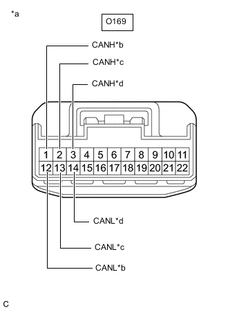
*a Front view of wire harness connector
(to No. 10 CAN Junction Connector)
*b to No. 8 CAN Junction Connector *c to Roll Rate and Vertical Acceleration Sensor *d to ECM Disconnect the O169 No. 10 CAN junction connector.
-
Measure the resistance according to the value(s) in the table below.
Standard Resistance Tester Connection Condition Specified Condition Connected to O169-1 (CANH) - O169-12 (CANL) Cable disconnected from negative (-) battery terminal 108 to 132 Ω No. 8 CAN junction connector O169-2 (CANH) - O169-13 (CANL) Cable disconnected from negative (-) battery terminal 200 Ω or higher Roll rate and vertical acceleration sensor O169-3 (CANH) - O169-14 (CANL) Cable disconnected from negative (-) battery terminal 108 to 132 Ω ECM Result Result Proceed to OK A NG (ECM main lines) B NG (ECU or sensor branch lines) C NG (No. 8 CAN junction connector main lines) D
- A
REPLACE NO. 10 CAN JUNCTION CONNECTOR
- B
REPAIR OR REPLACE CAN MAIN BUS LINES OR CONNECTOR (ECM - NO. 10 CAN JUNCTION CONNECTOR)
- CClick here
- DClick here
-
- Click here
CHECK FOR SHORT IN V3 BUS LINES (ECU OR SENSOR)
-
Reconnect all wire harness connectors.
-
Disconnect the connector that includes terminals CANH and CANL from the ECU or sensor to which the short circuited branch line is connected.
-
*a Component with harness connected
(No. 10 CAN Junction Connector)
Measure the resistance according to the value(s) in the table below.
Standard Resistance Tester Connection Condition Specified Condition O169-1 (CANH) - O169-12 (CANL) Cable disconnected from negative (-) battery terminal 54 to 69 Ω Tip:If the resistance becomes normal (between 54 and 69 Ω) when the connector is disconnected from the ECU or sensor, there may be a short in the ECU or sensor.
Result Result OK NG
- OK
REPLACE ECU OR SENSOR
- NG
REPAIR OR REPLACE ECU OR SENSOR BRANCH LINES OR CONNECTOR
-
- Click here
CHECK FOR SHORT IN V3 BUS LINES (NO. 8 CAN JUNCTION CONNECTOR)
-
Reconnect the O169 No. 10 CAN junction connector.
-
*a Front view of wire harness connector
(to No. 8 CAN Junction Connector)
*b to Skid Control ECU (Brake Actuator Assembly) *c to No. 10 CAN Junction Connector Disconnect the T44 No. 8 CAN junction connector.
-
Measure the resistance according to the value(s) in the table below.
Standard Resistance Tester Connection Condition Specified Condition Connected to T44-3 (CANH) - T44-14 (CANL) Cable disconnected from negative (-) battery terminal 108 to 132 Ω Skid control ECU (brake actuator assembly) T44-4 (CANH) - T44-15 (CANL) Cable disconnected from negative (-) battery terminal 108 to 132 Ω No. 10 CAN junction connector Result Result Proceed to OK A NG (Skid control ECU (brake actuator assembly) main lines) B NG (No. 10 CAN junction connector main lines) C
- A
REPLACE NO. 8 CAN JUNCTION CONNECTOR
- B
REPAIR OR REPLACE CAN MAIN BUS LINES OR CONNECTOR (SKID CONTROL ECU (BRAKE ACTUATOR ASSEMBLY) - NO. 8 CAN JUNCTION CONNECTOR)
- C
REPAIR OR REPLACE CAN MAIN BUS LINES OR CONNECTOR (NO. 8 CAN JUNCTION CONNECTOR - NO. 10 CAN JUNCTION CONNECTOR)
-
- Click here
CHECK FOR SHORT IN V3 BUS LINE (NO. 10 CAN JUNCTION CONNECTOR)
-
Disconnect the O169 No. 10 CAN junction connector.
-
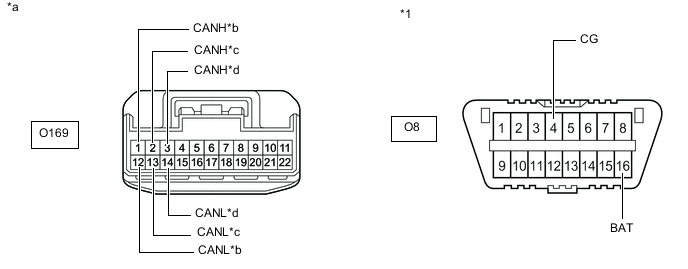
*1 DLC3 - - *a Front view of wire harness connector
(to No. 10 CAN Junction Connector)
*b to No. 8 CAN Junction Connector *c to Roll Rate and Vertical Acceleration Sensor *d to ECM Measure the resistance according to the value(s) in the table below.
Standard Resistance Tester Connection Condition Specified Condition Result Connected to O169-1 (CANH) - O8-4 (CG) Cable disconnected from negative (-) battery terminal 200 Ω or higher Below 200 Ω: CANH short to ground No. 8 CAN junction connector O169-12 (CANL) - O8-4 (CG) Cable disconnected from negative (-) battery terminal 200 Ω or higher Below 200 Ω: CANL short to ground O169-2 (CANH) - O8-4 (CG) Cable disconnected from negative (-) battery terminal 200 Ω or higher Below 200 Ω: CANH short to ground Roll rate and vertical acceleration sensor O169-13 (CANL) - O8-4 (CG) Cable disconnected from negative (-) battery terminal 200 Ω or higher Below 200 Ω: CANL short to ground O169-3 (CANH) - O8-4 (CG) Cable disconnected from negative (-) battery terminal 200 Ω or higher Below 200 Ω: CANH short to ground ECM O169-14 (CANL) - O8-4 (CG) Cable disconnected from negative (-) battery terminal 200 Ω or higher Below 200 Ω: CANL short to ground O169-1 (CANH) - O8-16 (BAT) Cable disconnected from negative (-) battery terminal 6 kΩ or higher Below 6 kΩ: CANH +B short No. 8 CAN junction connector O169-12 (CANL) - O8-16 (BAT) Cable disconnected from negative (-) battery terminal 6 kΩ or higher Below 6 kΩ: CANL +B short O169-2 (CANH) - O8-16 (BAT) Cable disconnected from negative (-) battery terminal 6 kΩ or higher Below 6 kΩ: CANH +B short Roll rate and vertical acceleration sensor O169-13 (CANL) - O8-16 (BAT) Cable disconnected from negative (-) battery terminal 6 kΩ or higher Below 6 kΩ: CANL +B short O169-3 (CANH) - O8-16 (BAT) Cable disconnected from negative (-) battery terminal 6 kΩ or higher Below 6 kΩ: CANH +B short ECM O169-14 (CANL) - O8-16 (BAT) Cable disconnected from negative (-) battery terminal 6 kΩ or higher Below 6 kΩ: CANL +B short Tip:
-
It is only necessary to perform the inspection in the above table for the result (short circuit) that was obtained in the Check V3 Bus inspection.
-
Find the necessary inspection from the Result column that matches the result in the Result column from the Check V3 Bus inspection.
Result Result Proceed to OK A NG (ECU or sensor CAN bus line) B NG (No. 8 CAN junction connector main line) C -
- A
REPLACE NO. 10 CAN JUNCTION CONNECTOR
- BClick here
GO TO STEP 16
- CClick here
-
- Click here
CHECK FOR SHORT IN V3 BUS LINE (NO. 8 CAN JUNCTION CONNECTOR)
-
Reconnect the O169 No. 10 CAN junction connector.
-
Disconnect the T44 No. 8 CAN junction connector.
-
*1 DLC3 - - *a Front view of wire harness connector
(to No. 8 CAN Junction Connector)
*b to Skid Control ECU (Brake Actuator Assembly) *c to No. 10 CAN Junction Connector - - Measure the resistance according to the value(s) in the table below.
Standard Resistance Tester Connection Condition Specified Condition Result Connected to T44-3 (CANH) - O8-4 (CG) Cable disconnected from negative (-) battery terminal 200 Ω or higher Below 200 Ω: CANH short to ground Skid control ECU (brake actuator assembly) T44-14 (CANL) - O8-4 (CG) Cable disconnected from negative (-) battery terminal 200 Ω or higher Below 200 Ω: CANL short to ground T44-4 (CANH) - O8-4 (CG) Cable disconnected from negative (-) battery terminal 200 Ω or higher Below 200 Ω: CANH short to ground No. 10 CAN junction connector T44-15 (CANL) - O8-4 (CG) Cable disconnected from negative (-) battery terminal 200 Ω or higher Below 200 Ω: CANL short to ground T44-3 (CANH) - O8-16 (BAT) Cable disconnected from negative (-) battery terminal 6 kΩ or higher Below 6 kΩ: CANH +B short Skid control ECU (brake actuator assembly) T44-14 (CANL) - O8-16 (BAT) Cable disconnected from negative (-) battery terminal 6 kΩ or higher Below 6 kΩ: CANL +B short T44-4 (CANH) - O8-16 (BAT) Cable disconnected from negative (-) battery terminal 6 kΩ or higher Below 6 kΩ: CANH +B short No. 10 CAN junction connector T44-15 (CANL) - O8-16 (BAT) Cable disconnected from negative (-) battery terminal 6 kΩ or higher Below 6 kΩ: CANL +B short Tip:
-
It is only necessary to perform the inspection in the above table for the result (short circuit) that was obtained in the Check V3 Bus inspection.
-
Find the necessary inspection from the Result column that matches the result in the Result column from the Check V3 Bus inspection.
Result Result Proceed to OK A NG (ECU or sensor CAN bus line) B NG (No. 10 CAN junction connector main line) C -
- A
REPLACE NO. 8 CAN JUNCTION CONNECTOR
- BClick here
- C
REPAIR OR REPLACE CAN MAIN BUS LINE OR CONNECTOR (NO. 8 CAN JUNCTION CONNECTOR - NO. 10 CAN JUNCTION CONNECTOR)
-
- Click here
CHECK FOR SHORT IN V3 BUS LINE (ECU, SENSOR)
-
Reconnect all wire harness connectors.
-
Disconnect the connector that includes terminals CANH and CANL from the ECU or sensor to which the bus line shorted to +B or shorted to GND is connected.
-

*1 DLC3 - - *a Component with harness connected
(No. 10 CAN Junction Connector)
- - Measure the resistance according to the value(s) in the table below.
Standard Resistance Tester Connection Condition Specified Condition Result O169-1 (CANH) - O8-4 (CG) Cable disconnected from negative (-) battery terminal 200 Ω or higher Below 200 Ω: CANH short to ground O169-12 (CANL) - O8-4 (CG) Cable disconnected from negative (-) battery terminal 200 Ω or higher Below 200 Ω: CANL short to ground O169-1 (CANH) - O8-16 (BAT) Cable disconnected from negative (-) battery terminal 6 kΩ or higher Below 6 kΩ: CANH +B short O169-12 (CANL) - O8-16 (BAT) Cable disconnected from negative (-) battery terminal 6 kΩ or higher Below 6 kΩ: CANL +B short Tip:
-
It is only necessary to perform the inspection in the above table for the result (short circuit) that was obtained in the Check V3 Bus inspection.
-
If the resistance becomes normal when the connector is disconnected from the ECU or sensor, there may be a short in the ECU or sensor.
-
Find the necessary inspection from the Result column that matches the result in the Result column from the Check V3 Bus inspection.
Result Result OK NG -
- OK
REPLACE ECU OR SENSOR
- NG
REPAIR OR REPLACE ECU OR SENSOR CAN BUS LINE OR CONNECTOR
-
- Click here
RECONFIRM DTC OUTPUT
-
Reconfirm DTCs.
- Chassis > ABS/VSC/TRC > Trouble Codes
-
-
- Chassis > TVD > Trouble Codes
-
-
Result Result Proceed to DTC U110F is output from the skid control ECU (brake actuator assembly) (ABS/VSC/TRAC) and DTC U1172 is output from the torque vectoring differential ECU assembly (TVD). A DTC U110F is output only from the skid control ECU (brake actuator assembly) (ABS/VSC/TRAC). B DTC U1172 is output only from the torque vectoring differential ECU assembly (TVD). C
-
- Click here
CHECK V3 BUS
-
Disconnect the cable from the negative (-) battery terminal.
-
*1 DLC3 - - *a Component with harness connected
(No. 10 CAN Junction Connector)
- - Measure the resistance according to the value(s) in the table below.
Standard Resistance Tester Connection Condition Specified Condition Result O169-1 (CANH) - O169-12 (CANL) Cable disconnected from negative (-) battery terminal 54 to 69 Ω Below 54 Ω: Short circuit between bus lines 70 Ω or higher: Open circuit in main bus lines O169-1 (CANH) - O8-4 (CG) Cable disconnected from negative (-) battery terminal 200 Ω or higher Below 200 Ω: CANH short to ground O169-12 (CANL) - O8-4 (CG) Cable disconnected from negative (-) battery terminal 200 Ω or higher Below 200 Ω: CANL short to ground O169-1 (CANH) - O8-16 (BAT) Cable disconnected from negative (-) battery terminal 6 kΩ or higher Below 6 kΩ: CANH +B short O169-12 (CANL) - O8-16 (BAT) Cable disconnected from negative (-) battery terminal 6 kΩ or higher Below 6 kΩ: CANL +B short Result Result Proceed to Open circuit in CAN main bus lines A Short circuit between bus lines B
-
Short to ground
-
+B short
C -
-
- Click here
CHECK FOR OPEN IN V3 BUS MAIN LINES (NO. 8 CAN JUNCTION CONNECTOR)
-
*a Front view of wire harness connector
(to No. 8 CAN Junction Connector)
Disconnect the T44 No. 8 CAN junction connector.
-
Measure the resistance according to the value(s) in the table below.
Standard Resistance Tester Connection Condition Specified Condition Connected to T44-3 (CANH) - T44-14 (CANL) Cable disconnected from negative (-) battery terminal 108 to 132 Ω Skid control ECU (brake actuator assembly) Result Result OK NG
- OK
REPLACE NO. 8 CAN JUNCTION CONNECTOR
- NGClick here
-
- Click here
CHECK FOR OPEN IN V3 BUS MAIN LINES (SKID CONTROL ECU (BRAKE ACTUATOR ASSEMBLY))
-
Reconnect the T44 No. 8 CAN junction connector.
-
*a Front view of wire harness connector
(to Skid Control ECU (Brake Actuator Assembly))
Disconnect the A86 skid control ECU (brake actuator assembly) connector.
-
Measure the resistance according to the value(s) in the table below.
Standard Resistance Tester Connection Condition Specified Condition A86-36 (CA2H) - A86-37 (CA2L) Cable disconnected from negative (-) battery terminal 108 to 132 Ω Result Result OK NG
- OK
REPLACE SKID CONTROL ECU (BRAKE ACTUATOR ASSEMBLY)Click here
- NG
REPAIR OR REPLACE CAN MAIN BUS LINES OR CONNECTOR (SKID CONTROL ECU (BRAKE ACTUATOR ASSEMBLY) - NO. 8 CAN JUNCTION CONNECTOR)
-
- Click here
CHECK FOR SHORT IN V3 BUS LINES (SKID CONTROL ECU (BRAKE ACTUATOR ASSEMBLY))
-
*a Front view of wire harness connector
(to Skid Control ECU (Brake Actuator Assembly))
Disconnect the A86 skid control ECU (brake actuator assembly) connector.
-
Measure the resistance according to the value(s) in the table below.
Standard Resistance Tester Connection Condition Specified Condition A86-36 (CA2H) - A86-37 (CA2L) Cable disconnected from negative (-) battery terminal 108 to 132 Ω Result Result OK NG
- OK
REPLACE SKID CONTROL ECU (BRAKE ACTUATOR ASSEMBLY)Click here
- NGClick here
-
- Click here
CHECK FOR SHORT IN V3 BUS LINES (ECM)
-
Reconnect the A86 skid control ECU (brake actuator assembly) connector.
-
*a Front view of wire harness connector
(to ECM)
Disconnect the A78 ECM connector.
-
Measure the resistance according to the value(s) in the table below.
Standard Resistance Tester Connection Condition Specified Condition A78-11 (CANP) - A78-12 (CANN) Cable disconnected from negative (-) battery terminal 108 to 132 Ω Result Result OK NG
- OK
REPLACE ECMClick here
- NGClick here
-
- Click here
CHECK FOR SHORT IN V3 BUS LINES (NO. 10 CAN JUNCTION CONNECTOR)
-
Reconnect the A78 ECM connector.
-
*a Front view of wire harness connector
(to No. 10 CAN Junction Connector)
*b to No. 8 CAN Junction Connector *c to Roll Rate and Vertical Acceleration Sensor *d to ECM Disconnect the O169 No. 10 CAN junction connector.
-
Measure the resistance according to the value(s) in the table below.
Standard Resistance Tester Connection Condition Specified Condition Connected to O169-1 (CANH) - O169-12 (CANL) Cable disconnected from negative (-) battery terminal 108 to 132 Ω No. 8 CAN junction connector O169-2 (CANH) - O169-13 (CANL) Cable disconnected from negative (-) battery terminal 200 Ω or higher Roll rate and vertical acceleration sensor O169-3 (CANH) - O169-14 (CANL) Cable disconnected from negative (-) battery terminal 108 to 132 Ω ECM Result Result Proceed to OK A NG (ECM main lines) B NG (ECU or sensor branch lines) C NG (No. 8 CAN junction connector main lines) D
- A
REPLACE NO. 10 CAN JUNCTION CONNECTOR
- B
REPAIR OR REPLACE CAN MAIN BUS LINES OR CONNECTOR (ECM - NO. 10 CAN JUNCTION CONNECTOR)
- CClick here
GO TO STEP 25
- DClick here
-
- Click here
CHECK FOR SHORT IN V3 BUS LINES (NO. 8 CAN JUNCTION CONNECTOR)
-
Reconnect the O169 No. 10 CAN junction connector.
-
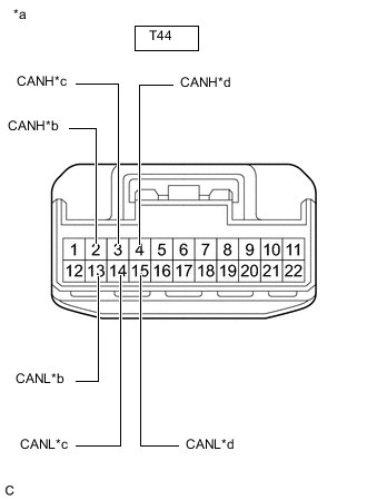
*a Front view of wire harness connector
(to No. 8 CAN Junction Connector)
*b to Torque Vectoring Differential ECU Assembly *c to Skid Control ECU (Brake Actuator Assembly) *d to No. 10 CAN Junction Connector Disconnect the T44 No. 8 CAN junction connector.
-
Measure the resistance according to the value(s) in the table below.
Standard Resistance Tester Connection Condition Specified Condition Connected to T44-2 (CANH) - T44-13 (CANL) Cable disconnected from negative (-) battery terminal 200 Ω or higher Torque vectoring differential ECU assembly T44-3 (CANH) - T44-14 (CANL) Cable disconnected from negative (-) battery terminal 108 to 132 Ω Skid control ECU (brake actuator assembly) T44-4 (CANH) - T44-15 (CANL) Cable disconnected from negative (-) battery terminal 108 to 132 Ω No. 10 CAN junction connector Result Result Proceed to OK A NG (Skid control ECU (brake actuator assembly) main lines) B NG (ECU or sensor branch lines) C NG (No. 10 CAN junction connector main lines) D
- A
REPLACE NO. 8 CAN JUNCTION CONNECTOR
- B
REPAIR OR REPLACE CAN MAIN BUS LINES OR CONNECTOR (SKID CONTROL ECU (BRAKE ACTUATOR ASSEMBLY) - NO. 8 CAN JUNCTION CONNECTOR)
- CClick here
- D
REPAIR OR REPLACE CAN MAIN BUS LINES OR CONNECTOR (NO. 8 CAN JUNCTION CONNECTOR - NO. 10 CAN JUNCTION CONNECTOR)
-
- Click here
CHECK FOR SHORT IN V3 BUS LINES (ECU OR SENSOR)
-
Reconnect all wire harness connectors.
-
Disconnect the connector that includes terminals CANH and CANL from the ECU or sensor to which the short circuited branch line is connected.
-
*a Component with harness connected
(No. 10 CAN Junction Connector)
Measure the resistance according to the value(s) in the table below.
Standard Resistance Tester Connection Condition Specified Condition O169-1 (CANH) - O169-12 (CANL) Cable disconnected from negative (-) battery terminal 54 to 69 Ω Tip:If the resistance becomes normal (between 54 and 69 Ω) when the connector is disconnected from the ECU or sensor, there may be a short in the ECU or sensor.
Result Result OK NG
- OK
REPLACE ECU OR SENSOR
- NG
REPAIR OR REPLACE ECU OR SENSOR BRANCH LINES OR CONNECTOR
-
- Click here
CHECK FOR SHORT IN V3 BUS LINE (NO. 10 CAN JUNCTION CONNECTOR)
-
Disconnect the O169 No. 10 CAN junction connector.
-
*1 DLC3 - - *a Front view of wire harness connector
(to No. 10 CAN Junction Connector)
*b to No. 8 CAN Junction Connector *c to Roll Rate and Vertical Acceleration Sensor *d to ECM Measure the resistance according to the value(s) in the table below.
Standard Resistance Tester Connection Condition Specified Condition Result Connected to O169-1 (CANH) - O8-4 (CG) Cable disconnected from negative (-) battery terminal 200 Ω or higher Below 200 Ω: CANH short to ground No. 8 CAN junction connector O169-12 (CANL) - O8-4 (CG) Cable disconnected from negative (-) battery terminal 200 Ω or higher Below 200 Ω: CANL short to ground O169-2 (CANH) - O8-4 (CG) Cable disconnected from negative (-) battery terminal 200 Ω or higher Below 200 Ω: CANH short to ground Roll rate and vertical acceleration sensor O169-13 (CANL) - O8-4 (CG) Cable disconnected from negative (-) battery terminal 200 Ω or higher Below 200 Ω: CANL short to ground O169-3 (CANH) - O8-4 (CG) Cable disconnected from negative (-) battery terminal 200 Ω or higher Below 200 Ω: CANH short to ground ECM O169-14 (CANL) - O8-4 (CG) Cable disconnected from negative (-) battery terminal 200 Ω or higher Below 200 Ω: CANL short to ground O169-1 (CANH) - O8-16 (BAT) Cable disconnected from negative (-) battery terminal 6 kΩ or higher Below 6 kΩ: CANH +B short No. 8 CAN junction connector O169-12 (CANL) - O8-16 (BAT) Cable disconnected from negative (-) battery terminal 6 kΩ or higher Below 6 kΩ: CANL +B short O169-2 (CANH) - O8-16 (BAT) Cable disconnected from negative (-) battery terminal 6 kΩ or higher Below 6 kΩ: CANH +B short Roll rate and vertical acceleration sensor O169-13 (CANL) - O8-16 (BAT) Cable disconnected from negative (-) battery terminal 6 kΩ or higher Below 6 kΩ: CANL +B short O169-3 (CANH) - O8-16 (BAT) Cable disconnected from negative (-) battery terminal 6 kΩ or higher Below 6 kΩ: CANH +B short ECM O169-14 (CANL) - O8-16 (BAT) Cable disconnected from negative (-) battery terminal 6 kΩ or higher Below 6 kΩ: CANL +B short Tip:
-
It is only necessary to perform the inspection in the above table for the result (short circuit) that was obtained in the Check V3 Bus inspection.
-
Find the necessary inspection from the Result column that matches the result in the Result column from the Check V3 Bus inspection.
Result Result Proceed to OK A NG (ECU or sensor CAN bus line) B NG (No. 8 CAN junction connector main line) C -
- A
REPLACE NO. 10 CAN JUNCTION CONNECTOR
- BClick here
GO TO STEP 28
- CClick here
-
- Click here
CHECK FOR SHORT IN V3 BUS LINE (NO. 8 CAN JUNCTION CONNECTOR)
-
Reconnect the O169 No. 10 CAN junction connector.
-
Disconnect the T44 No. 8 CAN junction connector.
-
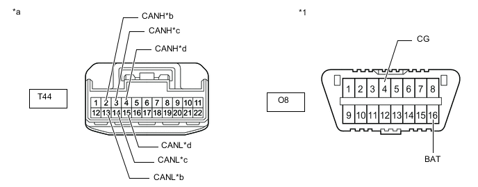
*1 DLC3 - - *a Front view of wire harness connector
(to No. 8 CAN Junction Connector)
*b to Torque Vectoring Differential ECU Assembly *c to Skid Control ECU (Brake Actuator Assembly) *d to No. 10 CAN Junction Connector Measure the resistance according to the value(s) in the table below.
Standard Resistance Tester Connection Condition Specified Condition Result Connected to T44-2 (CANH) - O8-4 (CG) Cable disconnected from negative (-) battery terminal 200 Ω or higher Below 200 Ω: CANH short to ground Torque vectoring differential ECU assembly T44-13 (CANL) - O8-4 (CG) Cable disconnected from negative (-) battery terminal 200 Ω or higher Below 200 Ω: CANL short to ground T44-3 (CANH) - O8-4 (CG) Cable disconnected from negative (-) battery terminal 200 Ω or higher Below 200 Ω: CANH short to ground Skid control ECU (brake actuator assembly) T44-14 (CANL) - O8-4 (CG) Cable disconnected from negative (-) battery terminal 200 Ω or higher Below 200 Ω: CANL short to ground T44-4 (CANH) - O8-4 (CG) Cable disconnected from negative (-) battery terminal 200 Ω or higher Below 200 Ω: CANH short to ground No. 10 CAN junction connector T44-15 (CANL) - O8-4 (CG) Cable disconnected from negative (-) battery terminal 200 Ω or higher Below 200 Ω: CANL short to ground T44-2 (CANH) - O8-16 (BAT) Cable disconnected from negative (-) battery terminal 6 kΩ or higher Below 6 kΩ: CANH +B short Torque vectoring differential ECU assembly T44-13 (CANL) - O8-16 (BAT) Cable disconnected from negative (-) battery terminal 6 kΩ or higher Below 6 kΩ: CANL +B short T44-3 (CANH) - O8-16 (BAT) Cable disconnected from negative (-) battery terminal 6 kΩ or higher Below 6 kΩ: CANH +B short Skid control ECU (brake actuator assembly) T44-14 (CANL) - O8-16 (BAT) Cable disconnected from negative (-) battery terminal 6 kΩ or higher Below 6 kΩ: CANL +B short T44-4 (CANH) - O8-16 (BAT) Cable disconnected from negative (-) battery terminal 6 kΩ or higher Below 6 kΩ: CANH +B short No. 10 CAN junction connector T44-15 (CANL) - O8-16 (BAT) Cable disconnected from negative (-) battery terminal 6 kΩ or higher Below 6 kΩ: CANL +B short Tip:
-
It is only necessary to perform the inspection in the above table for the result (short circuit) that was obtained in the Check V3 Bus inspection.
-
Find the necessary inspection from the Result column that matches the result in the Result column from the Check V3 Bus inspection.
Result Result Proceed to OK A NG (ECU or sensor CAN bus line) B NG (No. 10 CAN junction connector main line) C -
- A
REPLACE NO. 8 CAN JUNCTION CONNECTOR
- BClick here
- C
REPAIR OR REPLACE CAN MAIN BUS LINE OR CONNECTOR (NO. 8 CAN JUNCTION CONNECTOR - NO. 10 CAN JUNCTION CONNECTOR)
-
- Click here
CHECK FOR SHORT IN V3 BUS LINE (ECU, SENSOR)
-
Reconnect all wire harness connectors.
-
Disconnect the connector that includes terminals CANH and CANL from the ECU or sensor to which the bus line shorted to +B or shorted to GND is connected.
-
*1 DLC3 - - *a Component with harness connected
(No. 10 CAN Junction Connector)
- - Measure the resistance according to the value(s) in the table below.
Standard Resistance Tester Connection Condition Specified Condition Result O169-1 (CANH) - O8-4 (CG) Cable disconnected from negative (-) battery terminal 200 Ω or higher Below 200 Ω: CANH short to ground O169-12 (CANL) - O8-4 (CG) Cable disconnected from negative (-) battery terminal 200 Ω or higher Below 200 Ω: CANL short to ground O169-1 (CANH) - O8-16 (BAT) Cable disconnected from negative (-) battery terminal 6 kΩ or higher Below 6 kΩ: CANH +B short O169-12 (CANL) - O8-16 (BAT) Cable disconnected from negative (-) battery terminal 6 kΩ or higher Below 6 kΩ: CANL +B short Tip:
-
It is only necessary to perform the inspection in the above table for the result (short circuit) that was obtained in the Check V3 Bus inspection.
-
If the resistance becomes normal when the connector is disconnected from the ECU or sensor, there may be a short in the ECU or sensor.
-
Find the necessary inspection from the Result column that matches the result in the Result column from the Check V3 Bus inspection.
Result Result OK NG -
- OK
REPLACE ECU OR SENSOR
- NG
REPAIR OR REPLACE ECU OR SENSOR CAN BUS LINE OR CONNECTOR
-
- Click here
CHECK V3 BUS
-
Disconnect the cable from the negative (-) battery terminal.
-
*a Component with harness connected
(No. 10 CAN Junction Connector)
Measure the resistance according to the value(s) in the table below.
Standard Resistance Tester Connection Condition Specified Condition O169-1 (CANH) - O169-12 (CANL) Cable disconnected from negative (-) battery terminal 54 to 69 Ω Result Result OK NG
- OKClick here
- NGClick here
-
- Click here
CHECK FOR OPEN IN CAN BUS LINES (ROLL RATE AND VERTICAL ACCELERATION SENSOR BRANCH LINE)
-
*a Front view of wire harness connector
(to Roll Rate and Vertical Acceleration Sensor)
Disconnect the E1 yaw rate sensor connector.
-
Measure the resistance according to the value(s) in the table below.
Standard Resistance Tester Connection Condition Specified Condition E1-3 (YAW1) - E1-2 (YAW2) Cable disconnected from negative (-) battery terminal 54 to 69 Ω Result Result OK NG
- OK
REPLACE ROLL RATE AND VERTICAL ACCELERATION SENSORClick here
- NG
REPAIR OR REPLACE CAN BRANCH LINES OR CONNECTOR (ROLL RATE AND VERTICAL ACCELERATION SENSOR)
-
- Click here
CHECK FOR OPEN IN V3 BUS MAIN LINES (NO. 10 CAN JUNCTION CONNECTOR)
-
*a Front view of wire harness connector
(to No. 10 CAN Junction Connector)
*b to No. 8 CAN Junction Connector *c to ECM Disconnect the O169 No. 10 CAN junction connector.
-
Measure the resistance according to the value(s) in the table below.
Standard Resistance Tester Connection Condition Specified Condition Connected to O169-1 (CANH) - O169-12 (CANL) Cable disconnected from negative (-) battery terminal 108 to 132 Ω No. 8 CAN junction connector O169-3 (CANH) - O169-14 (CANL) Cable disconnected from negative (-) battery terminal 108 to 132 Ω ECM Result Result Proceed to OK A NG (ECM main lines) B NG (No. 8 CAN junction connector main lines) C
- A
REPLACE NO. 10 CAN JUNCTION CONNECTOR
- BClick here
- CClick here
-
- Click here
CHECK FOR OPEN IN V3 BUS MAIN LINES (ECM)
-
Reconnect the O169 No. 10 CAN junction connector.
-
*a Front view of wire harness connector
(to ECM)
Disconnect the A78 ECM connector.
-
Measure the resistance according to the value(s) in the table below.
Standard Resistance Tester Connection Condition Specified Condition A78-11 (CANP) - A78-12 (CANN) Cable disconnected from negative (-) battery terminal 108 to 132 Ω Result Result OK NG
- OK
REPLACE ECMClick here
- NG
REPAIR OR REPLACE CAN MAIN BUS LINES OR CONNECTOR (ECM - NO. 10 CAN JUNCTION CONNECTOR)
-
- Click here
CHECK FOR OPEN IN V3 BUS MAIN LINES (NO. 8 CAN JUNCTION CONNECTOR)
-
Reconnect the O169 No. 10 CAN junction connector.
-
*a Front view of wire harness connector
(to No. 8 CAN Junction Connector)
Disconnect the T44 No. 8 CAN junction connector.
-
Measure the resistance according to the value(s) in the table below.
Standard Resistance Tester Connection Condition Specified Condition Connected to T44-4 (CANH) - T44-15 (CANL) Cable disconnected from negative (-) battery terminal 108 to 132 Ω No. 8 CAN junction connector Result Result OK NG
- OK
REPLACE NO. 8 CAN JUNCTION CONNECTOR
- NG
REPAIR OR REPLACE CAN MAIN BUS LINES OR CONNECTOR (NO. 8 CAN JUNCTION CONNECTOR - NO. 10 CAN JUNCTION CONNECTOR)
-
- Click here
CHECK FOR OPEN IN CAN BUS LINES (TORQUE VECTORING DIFFERENTIAL ECU ASSEMBLY BRANCH LINE)
-
Disconnect the cable from the negative (-) battery terminal.
-
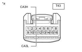
*a Front view of wire harness connector
(to Torque Vectoring Differential ECU Assembly)
Disconnect the T43 torque vectoring differential ECU assembly connector.
-
Measure the resistance according to the value(s) in the table below.
Standard Resistance Tester Connection Condition Specified Condition T43-3 (CA3H) - T43-11 (CA3L) Cable disconnected from negative (-) battery terminal 54 to 69 Ω Result Result OK NG
- OK
REPLACE TORQUE VECTORING DIFFERENTIAL ECU ASSEMBLYClick here
- NG
REPAIR OR REPLACE CAN BRANCH LINES OR CONNECTOR (TORQUE VECTORING DIFFERENTIAL ECU ASSEMBLY)
-
- Click here
CHECK VEHICLE TYPE
-
Check vehicle type.
Result Result Proceed to w/o Torque Vectoring Differential System A w/ Torque Vectoring Differential System B
-
- Click here
CHECK V3 BUS
-
Disconnect the cable from the negative (-) battery terminal.
-
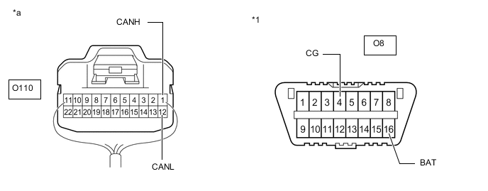
*1 DLC3 - - *a Component with harness connected
(No. 6 CAN Junction Connector)
- - Measure the resistance according to the value(s) in the table below.
Standard Resistance Tester Connection Condition Specified Condition Result O110-1 (CANH) - O110-12 (CANL) Cable disconnected from negative (-) battery terminal 54 to 69 Ω Below 54 Ω: Short circuit between bus lines 70 Ω or higher: Open circuit in main bus lines O110-1 (CANH) - O8-4 (CG) Cable disconnected from negative (-) battery terminal 200 Ω or higher Below 200 Ω: CANH short to ground O110-12 (CANL) - O8-4 (CG) Cable disconnected from negative (-) battery terminal 200 Ω or higher Below 200 Ω: CANL short to ground O110-1 (CANH) - O8-16 (BAT) Cable disconnected from negative (-) battery terminal 6 kΩ or higher Below 6 kΩ: CANH +B short O110-12 (CANL) - O8-16 (BAT) Cable disconnected from negative (-) battery terminal 6 kΩ or higher Below 6 kΩ: CANL +B short Result Result Proceed to OK A Open circuit in CAN main bus lines B Short circuit between bus lines C
-
Short to ground
-
+B short
D -
-
- Click here
CHECK FOR OPEN IN CAN BUS LINES (ROLL RATE AND VERTICAL ACCELERATION SENSOR BRANCH LINE)
-
*a Front view of wire harness connector
(to Roll Rate and Vertical Acceleration Sensor)
Disconnect the E1 yaw rate sensor connector.
-
Measure the resistance according to the value(s) in the table below.
Standard Resistance Tester Connection Condition Specified Condition E1-3 (YAW1) - E1-2 (YAW2) Cable disconnected from negative (-) battery terminal 54 to 69 Ω Result Result OK NG
- OK
REPLACE ROLL RATE AND VERTICAL ACCELERATION SENSORClick here
- NG
REPAIR OR REPLACE CAN BRANCH LINES OR CONNECTOR (ROLL RATE AND VERTICAL ACCELERATION SENSOR)
-
- Click here
CHECK FOR OPEN IN V3 BUS MAIN LINES (NO. 6 CAN JUNCTION CONNECTOR)
-

*a Front view of wire harness connector
(to No. 6 CAN Junction Connector)
*b to No. 8 CAN Junction Connector *c to ECM Disconnect the O110 No. 6 CAN junction connector.
-
Measure the resistance according to the value(s) in the table below.
Standard Resistance Tester Connection Condition Specified Condition Connected to O110-1 (CANH) - O110-12 (CANL) Cable disconnected from negative (-) battery terminal 108 to 132 Ω No. 8 CAN junction connector O110-3 (CANH) - O110-14 (CANL) Cable disconnected from negative (-) battery terminal 108 to 132 Ω ECM Result Result Proceed to OK A NG (ECM main lines) B NG (No. 8 CAN junction connector main lines) C
- A
REPLACE NO. 6 CAN JUNCTION CONNECTOR
- BClick here
- CClick here
-
- Click here
CHECK FOR OPEN IN V3 BUS MAIN LINES (ECM)
-
Reconnect the O110 No. 6 CAN junction connector.
-
*a Front view of wire harness connector
(to ECM)
Disconnect the A78 ECM connector.
-
Measure the resistance according to the value(s) in the table below.
Standard Resistance Tester Connection Condition Specified Condition A78-11 (CANP) - A78-12 (CANN) Cable disconnected from negative (-) battery terminal 108 to 132 Ω Result Result OK NG
- OK
REPLACE ECMClick here
- NG
REPAIR OR REPLACE CAN MAIN BUS LINES OR CONNECTOR (ECM - NO. 6 CAN JUNCTION CONNECTOR)
-
- Click here
CHECK FOR OPEN IN V3 BUS MAIN LINES (NO. 8 CAN JUNCTION CONNECTOR)
-
Reconnect the O110 No. 6 CAN junction connector.
-
*a Front view of wire harness connector
(to No. 8 CAN Junction Connector)
*b to Skid Control ECU (Brake Actuator Assembly) *c to No. 6 CAN Junction Connector Disconnect the T44 No. 8 CAN junction connector.
-
Measure the resistance according to the value(s) in the table below.
Standard Resistance Tester Connection Condition Specified Condition Connected to T44-3 (CANH) - T44-14 (CANL) Cable disconnected from negative (-) battery terminal 108 to 132 Ω Skid control ECU (brake actuator assembly) T44-4 (CANH) - T44-15 (CANL) Cable disconnected from negative (-) battery terminal 108 to 132 Ω No. 6 CAN junction connector Result Result Proceed to OK A NG (No. 6 CAN junction connector main lines) B NG (Skid control ECU (brake actuator assembly) main lines) C
- A
REPLACE NO. 8 CAN JUNCTION CONNECTOR
- B
REPAIR OR REPLACE CAN MAIN BUS LINES OR CONNECTOR (NO. 6 CAN JUNCTION CONNECTOR - NO. 8 CAN JUNCTION CONNECTOR)
- CClick here
-
- Click here
CHECK FOR OPEN IN V3 BUS MAIN LINES (SKID CONTROL ECU (BRAKE ACTUATOR ASSEMBLY))
-
Reconnect the T44 No. 8 CAN junction connector.
-
*a Front view of wire harness connector
(to Skid Control ECU (Brake Actuator Assembly))
Disconnect the A86 skid control ECU (brake actuator assembly) connector.
-
Measure the resistance according to the value(s) in the table below.
Standard Resistance Tester Connection Condition Specified Condition A86-36 (CA2H) - A86-37 (CA2L) Cable disconnected from negative (-) battery terminal 108 to 132 Ω Result Result OK NG
- OK
REPLACE SKID CONTROL ECU (BRAKE ACTUATOR ASSEMBLY)Click here
- NG
REPAIR OR REPLACE CAN MAIN BUS LINES OR CONNECTOR (SKID CONTROL ECU (BRAKE ACTUATOR ASSEMBLY) - NO. 8 CAN JUNCTION CONNECTOR)
-
- Click here
CHECK FOR SHORT IN V3 BUS LINES (SKID CONTROL ECU (BRAKE ACTUATOR ASSEMBLY))
-
*a Front view of wire harness connector
(to Skid Control ECU (Brake Actuator Assembly))
Disconnect the A86 skid control ECU (brake actuator assembly) connector.
-
Measure the resistance according to the value(s) in the table below.
Standard Resistance Tester Connection Condition Specified Condition A86-36 (CA2H) - A86-37 (CA2L) Cable disconnected from negative (-) battery terminal 108 to 132 Ω Result Result OK NG
- OK
REPLACE SKID CONTROL ECU (BRAKE ACTUATOR ASSEMBLY)Click here
- NGClick here
-
- Click here
CHECK FOR SHORT IN V3 BUS LINES (ECM)
-
Reconnect the A86 skid control ECU (brake actuator assembly) connector.
-
*a Front view of wire harness connector
(to ECM)
Disconnect the A78 ECM connector.
-
Measure the resistance according to the value(s) in the table below.
Standard Resistance Tester Connection Condition Specified Condition A78-11 (CANP) - A78-12 (CANN) Cable disconnected from negative (-) battery terminal 108 to 132 Ω Result Result OK NG
- OK
REPLACE ECMClick here
- NGClick here
-
- Click here
CHECK FOR SHORT IN V3 BUS LINES (NO. 6 CAN JUNCTION CONNECTOR)
-
Reconnect the A78 ECM connector.
-

*a Front view of wire harness connector
(to No. 6 CAN Junction Connector)
*b to No. 8 CAN Junction Connector *c to Roll Rate and Vertical Acceleration Sensor *d to ECM Disconnect the O110 No. 6 CAN junction connector.
-
Measure the resistance according to the value(s) in the table below.
Standard Resistance Tester Connection Condition Specified Condition Connected to O110-1 (CANH) - O110-12 (CANL) Cable disconnected from negative (-) battery terminal 108 to 132 Ω No. 8 CAN junction connector O110-2 (CANH) - O110-13 (CANL) Cable disconnected from negative (-) battery terminal 200 Ω or higher Roll rate and vertical acceleration sensor O110-3 (CANH) - O110-14 (CANL) Cable disconnected from negative (-) battery terminal 108 to 132 Ω ECM Result Result Proceed to OK A NG (ECM main lines) B NG (ECU or sensor branch lines) C NG (No. 8 CAN junction connector main lines) D
- A
REPLACE NO. 6 CAN JUNCTION CONNECTOR
- B
REPAIR OR REPLACE CAN MAIN BUS LINES OR CONNECTOR (ECM - NO. 6 CAN JUNCTION CONNECTOR)
- CClick here
- DClick here
-
- Click here
CHECK FOR SHORT IN V3 BUS LINES (ECU OR SENSOR)
-
Reconnect all wire harness connectors.
-
Disconnect the connector that includes terminals CANH and CANL from the ECU or sensor to which the short circuited branch line is connected.
-

*a Component with harness connected
(No. 6 CAN Junction Connector)
Measure the resistance according to the value(s) in the table below.
Standard Resistance Tester Connection Condition Specified Condition O110-1 (CANH) - O110-12 (CANL) Cable disconnected from negative (-) battery terminal 54 to 69 Ω Tip:If the resistance becomes normal (between 54 and 69 Ω) when the connector is disconnected from the ECU or sensor, there may be a short in the ECU or sensor.
Result Result OK NG
- OK
REPLACE ECU OR SENSOR
- NG
REPAIR OR REPLACE ECU OR SENSOR BRANCH LINES OR CONNECTOR
-
- Click here
CHECK FOR SHORT IN V3 BUS LINES (NO. 8 CAN JUNCTION CONNECTOR)
-
Reconnect the O110 No. 6 CAN junction connector.
-
*a Front view of wire harness connector
(to No. 8 CAN Junction Connector)
*b to Skid Control ECU (Brake Actuator Assembly) *c to No. 6 CAN Junction Connector Disconnect the T44 No. 8 CAN junction connector.
-
Measure the resistance according to the value(s) in the table below.
Standard Resistance Tester Connection Condition Specified Condition Connected to T44-3 (CANH) - T44-14 (CANL) Cable disconnected from negative (-) battery terminal 108 to 132 Ω Skid control ECU (brake actuator assembly) T44-4 (CANH) - T44-15 (CANL) Cable disconnected from negative (-) battery terminal 108 to 132 Ω No. 6 CAN junction connector Result Result Proceed to OK A NG (Skid control ECU (brake actuator assembly) main lines) B NG (No. 6 CAN junction connector main lines) C
- A
REPLACE NO. 8 CAN JUNCTION CONNECTOR
- B
REPAIR OR REPLACE CAN MAIN BUS LINES OR CONNECTOR (SKID CONTROL ECU (BRAKE ACTUATOR ASSEMBLY) - NO. 8 CAN JUNCTION CONNECTOR)
- C
REPAIR OR REPLACE CAN MAIN BUS LINES OR CONNECTOR (NO. 6 CAN JUNCTION CONNECTOR - NO. 8 CAN JUNCTION CONNECTOR)
-
- Click here
CHECK FOR SHORT IN V3 BUS LINE (NO. 6 CAN JUNCTION CONNECTOR)
-
Disconnect the O110 No. 6 CAN junction connector.
-

*1 DLC3 - - *a Front view of wire harness connector
(to No. 6 CAN Junction Connector)
*b to No. 8 CAN Junction Connector *c to Roll Rate and Vertical Acceleration Sensor *d to ECM Measure the resistance according to the value(s) in the table below.
Standard Resistance Tester Connection Condition Specified Condition Result Connected to O110-1 (CANH) - O8-4 (CG) Cable disconnected from negative (-) battery terminal 200 Ω or higher Below 200 Ω: CANH short to ground No. 8 CAN junction connector O110-12 (CANL) - O8-4 (CG) Cable disconnected from negative (-) battery terminal 200 Ω or higher Below 200 Ω: CANL short to ground O110-2 (CANH) - O8-4 (CG) Cable disconnected from negative (-) battery terminal 200 Ω or higher Below 200 Ω: CANH short to ground Roll rate and vertical acceleration sensor O110-13 (CANL) - O8-4 (CG) Cable disconnected from negative (-) battery terminal 200 Ω or higher Below 200 Ω: CANL short to ground O110-3 (CANH) - O8-4 (CG) Cable disconnected from negative (-) battery terminal 200 Ω or higher Below 200 Ω: CANH short to ground ECM O110-14 (CANL) - O8-4 (CG) Cable disconnected from negative (-) battery terminal 200 Ω or higher Below 200 Ω: CANL short to ground O110-1 (CANH) - O8-16 (BAT) Cable disconnected from negative (-) battery terminal 6 kΩ or higher Below 6 kΩ: CANH +B short No. 8 CAN junction connector O110-12 (CANL) - O8-16 (BAT) Cable disconnected from negative (-) battery terminal 6 kΩ or higher Below 6 kΩ: CANL +B short O110-2 (CANH) - O8-16 (BAT) Cable disconnected from negative (-) battery terminal 6 kΩ or higher Below 6 kΩ: CANH +B short Roll rate and vertical acceleration sensor O110-13 (CANL) - O8-16 (BAT) Cable disconnected from negative (-) battery terminal 6 kΩ or higher Below 6 kΩ: CANL +B short O110-3 (CANH) - O8-16 (BAT) Cable disconnected from negative (-) battery terminal 6 kΩ or higher Below 6 kΩ: CANH +B short ECM O110-14 (CANL) - O8-16 (BAT) Cable disconnected from negative (-) battery terminal 6 kΩ or higher Below 6 kΩ: CANL +B short Tip:
-
It is only necessary to perform the inspection in the above table for the result (short circuit) that was obtained in the Check V3 Bus inspection.
-
Find the necessary inspection from the Result column that matches the result in the Result column from the Check V3 Bus inspection.
Result Result Proceed to OK A NG (ECU or sensor CAN bus line) B NG (No. 8 CAN junction connector main line) C -
- A
REPLACE NO. 6 CAN JUNCTION CONNECTOR
- BClick here
GO TO STEP 49
- CClick here
-
- Click here
CHECK FOR SHORT IN V3 BUS LINE (NO. 8 CAN JUNCTION CONNECTOR)
-
Reconnect the O110 No. 6 CAN junction connector.
-
Disconnect the T44 No. 8 CAN junction connector.
-
*1 DLC3 - - *a Front view of wire harness connector
(to No. 8 CAN Junction Connector)
*b to Skid Control ECU (Brake Actuator Assembly) *c to No. 6 CAN Junction Connector - - Measure the resistance according to the value(s) in the table below.
Standard Resistance Tester Connection Condition Specified Condition Result Connected to T44-3 (CANH) - O8-4 (CG) Cable disconnected from negative (-) battery terminal 200 Ω or higher Below 200 Ω: CANH short to ground Skid control ECU (brake actuator assembly) T44-14 (CANL) - O8-4 (CG) Cable disconnected from negative (-) battery terminal 200 Ω or higher Below 200 Ω: CANL short to ground T44-4 (CANH) - O8-4 (CG) Cable disconnected from negative (-) battery terminal 200 Ω or higher Below 200 Ω: CANH short to ground No. 6 CAN junction connector T44-15 (CANL) - O8-4 (CG) Cable disconnected from negative (-) battery terminal 200 Ω or higher Below 200 Ω: CANL short to ground T44-3 (CANH) - O8-16 (BAT) Cable disconnected from negative (-) battery terminal 6 kΩ or higher Below 6 kΩ: CANH +B short Skid control ECU (brake actuator assembly) T44-14 (CANL) - O8-16 (BAT) Cable disconnected from negative (-) battery terminal 6 kΩ or higher Below 6 kΩ: CANL +B short T44-4 (CANH) - O8-16 (BAT) Cable disconnected from negative (-) battery terminal 6 kΩ or higher Below 6 kΩ: CANH +B short No. 6 CAN junction connector T44-15 (CANL) - O8-16 (BAT) Cable disconnected from negative (-) battery terminal 6 kΩ or higher Below 6 kΩ: CANL +B short Tip:
-
It is only necessary to perform the inspection in the above table for the result (short circuit) that was obtained in the Check V3 Bus inspection.
-
Find the necessary inspection from the Result column that matches the result in the Result column from the Check V3 Bus inspection.
Result Result Proceed to OK A NG (ECU or sensor CAN bus line) B NG (No. 6 CAN junction connector main line) C -
- A
REPLACE NO. 8 CAN JUNCTION CONNECTOR
- BClick here
- C
REPAIR OR REPLACE CAN MAIN BUS LINE OR CONNECTOR (NO. 6 CAN JUNCTION CONNECTOR - NO. 8 CAN JUNCTION CONNECTOR)
-
- Click here
CHECK FOR SHORT IN V3 BUS LINE (ECU, SENSOR)
-
Reconnect all wire harness connectors.
-
Disconnect the connector that includes terminals CANH and CANL from the ECU or sensor to which the bus line shorted to +B or shorted to GND is connected.
-

*1 DLC3 - - *a Component with harness connected
(No. 6 CAN Junction Connector)
- - Measure the resistance according to the value(s) in the table below.
Standard Resistance Tester Connection Condition Specified Condition Result O110-1 (CANH) - O8-4 (CG) Cable disconnected from negative (-) battery terminal 200 Ω or higher Below 200 Ω: CANH short to ground O110-12 (CANL) - O8-4 (CG) Cable disconnected from negative (-) battery terminal 200 Ω or higher Below 200 Ω: CANL short to ground O110-1 (CANH) - O8-16 (BAT) Cable disconnected from negative (-) battery terminal 6 kΩ or higher Below 6 kΩ: CANH +B short O110-12 (CANL) - O8-16 (BAT) Cable disconnected from negative (-) battery terminal 6 kΩ or higher Below 6 kΩ: CANL +B short Tip:
-
It is only necessary to perform the inspection in the above table for the result (short circuit) that was obtained in the Check V3 Bus inspection.
-
If the resistance becomes normal when the connector is disconnected from the ECU or sensor, there may be a short in the ECU or sensor.
-
Find the necessary inspection from the Result column that matches the result in the Result column from the Check V3 Bus inspection.
Result Result OK NG -
- OK
REPLACE ECU OR SENSOR
- NG
REPAIR OR REPLACE ECU OR SENSOR CAN BUS LINE OR CONNECTOR
-
- Click here
RECONFIRM DTC OUTPUT
-
Reconfirm DTCs.
- Chassis > ABS/VSC/TRAC > Trouble Codes
-
-
- Chassis > TVD > Trouble Codes
-
-
Result Result Proceed to DTC U110F is output from the skid control ECU (brake actuator assembly) (ABS/VSC/TRAC) and DTC U1172 is output from the torque vectoring differential ECU assembly (TVD). A DTC U110F is output only from the skid control ECU (brake actuator assembly) (ABS/VSC/TRAC). B DTC U1172 is output only from the torque vectoring differential ECU assembly (TVD). C
-
- Click here
CHECK V3 BUS
-
Disconnect the cable from the negative (-) battery terminal.
-
*1 DLC3 - - *a Component with harness connected
(No. 6 CAN Junction Connector)
- - Measure the resistance according to the value(s) in the table below.
Standard Resistance Tester Connection Condition Specified Condition Result O110-1 (CANH) - O110-12 (CANL) Cable disconnected from negative (-) battery terminal 54 to 69 Ω Below 54 Ω: Short circuit between bus lines 70 Ω or higher: Open circuit in main bus lines O110-1 (CANH) - O8-4 (CG) Cable disconnected from negative (-) battery terminal 200 Ω or higher Below 200 Ω: CANH short to ground O110-12 (CANL) - O8-4 (CG) Cable disconnected from negative (-) battery terminal 200 Ω or higher Below 200 Ω: CANL short to ground O110-1 (CANH) - O8-16 (BAT) Cable disconnected from negative (-) battery terminal 6 kΩ or higher Below 6 kΩ: CANH +B short O110-12 (CANL) - O8-16 (BAT) Cable disconnected from negative (-) battery terminal 6 kΩ or higher Below 6 kΩ: CANL +B short Result Result Proceed to Open circuit in CAN main bus lines A Short circuit between bus lines B
-
Short to ground
-
+B short
C -
-
- Click here
CHECK FOR OPEN IN V3 BUS MAIN LINES (NO. 8 CAN JUNCTION CONNECTOR)
-
*a Front view of wire harness connector
(to No. 8 CAN Junction Connector)
Disconnect the T44 No. 8 CAN junction connector.
-
Measure the resistance according to the value(s) in the table below.
Standard Resistance Tester Connection Condition Specified Condition Connected to T44-3 (CANH) - T44-14 (CANL) Cable disconnected from negative (-) battery terminal 108 to 132 Ω Skid control ECU (brake actuator assembly) Result Result OK NG
- OK
REPLACE NO. 8 CAN JUNCTION CONNECTOR
- NGClick here
-
- Click here
CHECK FOR OPEN IN V3 BUS MAIN LINES (SKID CONTROL ECU (BRAKE ACTUATOR ASSEMBLY))
-
Reconnect the T44 No. 8 CAN junction connector.
-
*a Front view of wire harness connector
(to Skid Control ECU (Brake Actuator Assembly))
Disconnect the A86 skid control ECU (brake actuator assembly) connector.
-
Measure the resistance according to the value(s) in the table below.
Standard Resistance Tester Connection Condition Specified Condition A86-36 (CA2H) - A86-37 (CA2L) Cable disconnected from negative (-) battery terminal 108 to 132 Ω Result Result OK NG
- OK
REPLACE SKID CONTROL ECU (BRAKE ACTUATOR ASSEMBLY)Click here
- NG
REPAIR OR REPLACE CAN MAIN BUS LINES OR CONNECTOR (SKID CONTROL ECU (BRAKE ACTUATOR ASSEMBLY) - NO. 8 CAN JUNCTION CONNECTOR)
-
- Click here
CHECK FOR SHORT IN V3 BUS LINES (SKID CONTROL ECU (BRAKE ACTUATOR ASSEMBLY))
-
*a Front view of wire harness connector
(to Skid Control ECU (Brake Actuator Assembly))
Disconnect the A86 skid control ECU (brake actuator assembly) connector.
-
Measure the resistance according to the value(s) in the table below.
Standard Resistance Tester Connection Condition Specified Condition A86-36 (CA2H) - A86-37 (CA2L) Cable disconnected from negative (-) battery terminal 108 to 132 Ω Result Result OK NG
- OK
REPLACE SKID CONTROL ECU (BRAKE ACTUATOR ASSEMBLY)Click here
- NGClick here
-
- Click here
CHECK FOR SHORT IN V3 BUS LINES (ECM)
-
Reconnect the A86 skid control ECU (brake actuator assembly) connector.
-
*a Front view of wire harness connector
(to ECM)
Disconnect the A78 ECM connector.
-
Measure the resistance according to the value(s) in the table below.
Standard Resistance Tester Connection Condition Specified Condition A78-11 (CANP) - A78-12 (CANN) Cable disconnected from negative (-) battery terminal 108 to 132 Ω Result Result OK NG
- OK
REPLACE ECMClick here
- NGClick here
-
- Click here
CHECK FOR SHORT IN V3 BUS LINES (NO. 6 CAN JUNCTION CONNECTOR)
-
Reconnect the A78 ECM connector.
-

*a Front view of wire harness connector
(to No. 6 CAN Junction Connector)
*b to No. 8 CAN Junction Connector *c to Roll Rate and Vertical Acceleration Sensor *d to ECM Disconnect the O110 No. 6 CAN junction connector.
-
Measure the resistance according to the value(s) in the table below.
Standard Resistance Tester Connection Condition Specified Condition Connected to O110-1 (CANH) - O110-12 (CANL) Cable disconnected from negative (-) battery terminal 108 to 132 Ω No. 8 CAN junction connector O110-2 (CANH) - O110-13 (CANL) Cable disconnected from negative (-) battery terminal 200 Ω or higher Roll rate and vertical acceleration sensor O110-3 (CANH) - O110-14 (CANL) Cable disconnected from negative (-) battery terminal 108 to 132 Ω ECM Result Result Proceed to OK A NG (ECM main lines) B NG (ECU or sensor branch lines) C NG (No. 8 CAN junction connector main lines) D
- A
REPLACE NO. 6 CAN JUNCTION CONNECTOR
- B
REPAIR OR REPLACE CAN MAIN BUS LINES OR CONNECTOR (ECM - NO. 6 CAN JUNCTION CONNECTOR)
- CClick here
GO TO STEP 58
- DClick here
-
- Click here
CHECK FOR SHORT IN V3 BUS LINES (NO. 8 CAN JUNCTION CONNECTOR)
-
Reconnect the O110 No. 6 CAN junction connector.
-
*a Front view of wire harness connector
(to No. 8 CAN Junction Connector)
*b to Torque Vectoring Differential ECU Assembly *c to Skid Control ECU (Brake Actuator Assembly) *d to No. 6 CAN Junction Connector Disconnect the T44 No. 8 CAN junction connector.
-
Measure the resistance according to the value(s) in the table below.
Standard Resistance Tester Connection Condition Specified Condition Connected to T44-2 (CANH) - T44-13 (CANL) Cable disconnected from negative (-) battery terminal 200 Ω or higher Torque vectoring differential ECU assembly T44-3 (CANH) - T44-14 (CANL) Cable disconnected from negative (-) battery terminal 108 to 132 Ω Skid control ECU (brake actuator assembly) T44-4 (CANH) - T44-15 (CANL) Cable disconnected from negative (-) battery terminal 108 to 132 Ω No. 6 CAN junction connector Result Result Proceed to OK A NG (Skid control ECU (brake actuator assembly) main lines) B NG (ECU or sensor branch lines) C NG (No. 6 CAN junction connector main lines) D
- A
REPLACE NO. 8 CAN JUNCTION CONNECTOR
- B
REPAIR OR REPLACE CAN MAIN BUS LINES OR CONNECTOR (SKID CONTROL ECU (BRAKE ACTUATOR ASSEMBLY) - NO. 8 CAN JUNCTION CONNECTOR)
- CClick here
- D
REPAIR OR REPLACE CAN MAIN BUS LINES OR CONNECTOR (NO. 6 CAN JUNCTION CONNECTOR - NO. 8 CAN JUNCTION CONNECTOR)
-
- Click here
CHECK FOR SHORT IN V3 BUS LINES (ECU OR SENSOR)
-
Reconnect all wire harness connectors.
-
Disconnect the connector that includes terminals CANH and CANL from the ECU or sensor to which the short circuited branch line is connected.
-

*a Component with harness connected
(No. 8 CAN Junction Connector)
Measure the resistance according to the value(s) in the table below.
Standard Resistance Tester Connection Condition Specified Condition O110-1 (CANH) - O110-12 (CANL) Cable disconnected from negative (-) battery terminal 54 to 69 Ω Tip:If the resistance becomes normal (between 54 and 69 Ω) when the connector is disconnected from the ECU or sensor, there may be a short in the ECU or sensor.
Result Result OK NG
- OK
REPLACE ECU OR SENSOR
- NG
REPAIR OR REPLACE ECU OR SENSOR BRANCH LINES OR CONNECTOR
-
- Click here
CHECK FOR SHORT IN V3 BUS LINE (NO. 6 CAN JUNCTION CONNECTOR)
-
Disconnect the O110 No. 6 CAN junction connector.
-

*1 DLC3 - - *a Front view of wire harness connector
(to No. 6 CAN Junction Connector)
*b to No. 8 CAN Junction Connector *c to Roll Rate and Vertical Acceleration Sensor *d to ECM Measure the resistance according to the value(s) in the table below.
Standard Resistance Tester Connection Condition Specified Condition Result Connected to O110-1 (CANH) - O8-4 (CG) Cable disconnected from negative (-) battery terminal 200 Ω or higher Below 200 Ω: CANH short to ground No. 8 CAN junction connector O110-12 (CANL) - O8-4 (CG) Cable disconnected from negative (-) battery terminal 200 Ω or higher Below 200 Ω: CANL short to ground O110-2 (CANH) - O8-4 (CG) Cable disconnected from negative (-) battery terminal 200 Ω or higher Below 200 Ω: CANH short to ground Roll rate and vertical acceleration sensor O110-13 (CANL) - O8-4 (CG) Cable disconnected from negative (-) battery terminal 200 Ω or higher Below 200 Ω: CANL short to ground O110-3 (CANH) - O8-4 (CG) Cable disconnected from negative (-) battery terminal 200 Ω or higher Below 200 Ω: CANH short to ground ECM O110-14 (CANL) - O8-4 (CG) Cable disconnected from negative (-) battery terminal 200 Ω or higher Below 200 Ω: CANL short to ground O110-1 (CANH) - O8-16 (BAT) Cable disconnected from negative (-) battery terminal 6 kΩ or higher Below 6 kΩ: CANH +B short No. 8 CAN junction connector O110-12 (CANL) - O8-16 (BAT) Cable disconnected from negative (-) battery terminal 6 kΩ or higher Below 6 kΩ: CANL +B short O110-2 (CANH) - O8-16 (BAT) Cable disconnected from negative (-) battery terminal 6 kΩ or higher Below 6 kΩ: CANH +B short Roll rate and vertical acceleration sensor O110-13 (CANL) - O8-16 (BAT) Cable disconnected from negative (-) battery terminal 6 kΩ or higher Below 6 kΩ: CANL +B short O110-3 (CANH) - O8-16 (BAT) Cable disconnected from negative (-) battery terminal 6 kΩ or higher Below 6 kΩ: CANH +B short ECM O110-14 (CANL) - O8-16 (BAT) Cable disconnected from negative (-) battery terminal 6 kΩ or higher Below 6 kΩ: CANL +B short Tip:
-
It is only necessary to perform the inspection in the above table for the result (short circuit) that was obtained in the Check V3 Bus inspection.
-
Find the necessary inspection from the Result column that matches the result in the Result column from the Check V3 Bus inspection.
Result Result Proceed to OK A NG (ECU or sensor CAN bus line) B NG (No. 8 CAN junction connector main line) C -
- A
REPLACE NO. 6 CAN JUNCTION CONNECTOR
- BClick here
GO TO STEP 61
- CClick here
-
- Click here
CHECK FOR SHORT IN V3 BUS LINE (NO. 8 CAN JUNCTION CONNECTOR)
-
Reconnect the O110 No. 6 CAN junction connector.
-
Disconnect the T44 No. 8 CAN junction connector.
-
*1 DLC3 - - *a Front view of wire harness connector
(to No. 8 CAN Junction Connector)
*b to Torque Vectoring Differential ECU Assembly *c to Skid Control ECU (Brake Actuator Assembly) *d to No. 6 CAN Junction Connector Measure the resistance according to the value(s) in the table below.
Standard Resistance Tester Connection Condition Specified Condition Result Connected to T44-2 (CANH) - O8-4 (CG) Cable disconnected from negative (-) battery terminal 200 Ω or higher Below 200 Ω: CANH short to ground Torque vectoring differential ECU assembly T44-13 (CANL) - O8-4 (CG) Cable disconnected from negative (-) battery terminal 200 Ω or higher Below 200 Ω: CANL short to ground T44-3 (CANH) - O8-4 (CG) Cable disconnected from negative (-) battery terminal 200 Ω or higher Below 200 Ω: CANH short to ground Skid control ECU (brake actuator assembly) T44-14 (CANL) - O8-4 (CG) Cable disconnected from negative (-) battery terminal 200 Ω or higher Below 200 Ω: CANL short to ground T44-4 (CANH) - O8-4 (CG) Cable disconnected from negative (-) battery terminal 200 Ω or higher Below 200 Ω: CANH short to ground No. 6 CAN junction connector T44-15 (CANL) - O8-4 (CG) Cable disconnected from negative (-) battery terminal 200 Ω or higher Below 200 Ω: CANL short to ground T44-2 (CANH) - O8-16 (BAT) Cable disconnected from negative (-) battery terminal 6 kΩ or higher Below 6 kΩ: CANH +B short Torque vectoring differential ECU assembly T44-13 (CANL) - O8-16 (BAT) Cable disconnected from negative (-) battery terminal 6 kΩ or higher Below 6 kΩ: CANL +B short T44-3 (CANH) - O8-16 (BAT) Cable disconnected from negative (-) battery terminal 6 kΩ or higher Below 6 kΩ: CANH +B short Skid control ECU (brake actuator assembly) T44-14 (CANL) - O8-16 (BAT) Cable disconnected from negative (-) battery terminal 6 kΩ or higher Below 6 kΩ: CANL +B short T44-4 (CANH) - O8-16 (BAT) Cable disconnected from negative (-) battery terminal 6 kΩ or higher Below 6 kΩ: CANH +B short No. 6 CAN junction connector T44-15 (CANL) - O8-16 (BAT) Cable disconnected from negative (-) battery terminal 6 kΩ or higher Below 6 kΩ: CANL +B short Tip:
-
It is only necessary to perform the inspection in the above table for the result (short circuit) that was obtained in the Check V3 Bus inspection.
-
Find the necessary inspection from the Result column that matches the result in the Result column from the Check V3 Bus inspection.
Result Result Proceed to OK A NG (ECU or sensor CAN bus line) B NG (No. 6 CAN junction connector main line) C -
- A
REPLACE NO. 8 CAN JUNCTION CONNECTOR
- BClick here
- C
REPAIR OR REPLACE CAN MAIN BUS LINE OR CONNECTOR (NO. 6 CAN JUNCTION CONNECTOR - NO. 8 CAN JUNCTION CONNECTOR)
-
- Click here
CHECK FOR SHORT IN V3 BUS LINE (ECU, SENSOR)
-
Reconnect all wire harness connectors.
-
Disconnect the connector that includes terminals CANH and CANL from the ECU or sensor to which the bus line shorted to +B or shorted to GND is connected.
-

*1 DLC3 - - *a Component with harness connected
(No. 6 CAN Junction Connector)
- - Measure the resistance according to the value(s) in the table below.
Standard Resistance Tester Connection Condition Specified Condition Result O110-1 (CANH) - O8-4 (CG) Cable disconnected from negative (-) battery terminal 200 Ω or higher Below 200 Ω: CANH short to ground O110-12 (CANL) - O8-4 (CG) Cable disconnected from negative (-) battery terminal 200 Ω or higher Below 200 Ω: CANL short to ground O110-1 (CANH) - O8-16 (BAT) Cable disconnected from negative (-) battery terminal 6 kΩ or higher Below 6 kΩ: CANH +B short O110-12 (CANL) - O8-16 (BAT) Cable disconnected from negative (-) battery terminal 6 kΩ or higher Below 6 kΩ: CANL +B short Tip:
-
It is only necessary to perform the inspection in the above table for the result (short circuit) that was obtained in the Check V3 Bus inspection.
-
If the resistance becomes normal when the connector is disconnected from the ECU or sensor, there may be a short in the ECU or sensor.
-
Find the necessary inspection from the Result column that matches the result in the Result column from the Check V3 Bus inspection.
Result Result OK NG -
- OK
REPLACE ECU OR SENSOR
- NG
REPAIR OR REPLACE ECU OR SENSOR CAN BUS LINE OR CONNECTOR
-
- Click here
CHECK V3 BUS
-
Disconnect the cable from the negative (-) battery terminal.
-

*a Component with harness connected
(No. 6 CAN Junction Connector)
Measure the resistance according to the value(s) in the table below.
Standard Resistance Tester Connection Condition Specified Condition O110-1 (CANH) - O110-12 (CANL) Cable disconnected from negative (-) battery terminal 54 to 69 Ω Result Result OK NG
- OKClick here
- NGClick here
-
- Click here
CHECK FOR OPEN IN CAN BUS LINES (ROLL RATE AND VERTICAL ACCELERATION SENSOR BRANCH LINE)
-
*a Front view of wire harness connector
(to Roll Rate and Vertical Acceleration Sensor)
Disconnect the E1 yaw rate sensor connector.
-
Measure the resistance according to the value(s) in the table below.
Standard Resistance Tester Connection Condition Specified Condition E1-3 (YAW1) - E1-2 (YAW2) Cable disconnected from negative (-) battery terminal 54 to 69 Ω Result Result OK NG
- OK
REPLACE ROLL RATE AND VERTICAL ACCELERATION SENSORClick here
- NG
REPAIR OR REPLACE CAN BRANCH LINES OR CONNECTOR (ROLL RATE AND VERTICAL ACCELERATION SENSOR)
-
- Click here
CHECK FOR OPEN IN V3 BUS MAIN LINES (NO. 6 CAN JUNCTION CONNECTOR)
-
*a Front view of wire harness connector
(to No. 6 CAN Junction Connector)
*b to No. 8 CAN Junction Connector *c to ECM Disconnect the O110 No. 6 CAN junction connector.
-
Measure the resistance according to the value(s) in the table below.
Standard Resistance Tester Connection Condition Specified Condition Connected to O110-1 (CANH) - O110-12 (CANL) Cable disconnected from negative (-) battery terminal 108 to 132 Ω No. 8 CAN junction connector O110-3 (CANH) - O110-14 (CANL) Cable disconnected from negative (-) battery terminal 108 to 132 Ω ECM Result Result Proceed to OK A NG (ECM main lines) B NG (No. 8 CAN junction connector main lines) C
- A
REPLACE NO. 6 CAN JUNCTION CONNECTOR
- BClick here
- CClick here
-
- Click here
CHECK FOR OPEN IN V3 BUS MAIN LINES (ECM)
-
Reconnect the O110 No. 6 CAN junction connector.
-
*a Front view of wire harness connector
(to ECM)
Disconnect the A78 ECM connector.
-
Measure the resistance according to the value(s) in the table below.
Standard Resistance Tester Connection Condition Specified Condition A78-11 (CANP) - A78-12 (CANN) Cable disconnected from negative (-) battery terminal 108 to 132 Ω Result Result OK NG
- OK
REPLACE ECMClick here
- NG
REPAIR OR REPLACE CAN MAIN BUS LINES OR CONNECTOR (ECM - NO. 6 CAN JUNCTION CONNECTOR)
-
- Click here
CHECK FOR OPEN IN V3 BUS MAIN LINES (NO. 8 CAN JUNCTION CONNECTOR)
-
Reconnect the O110 No. 6 CAN junction connector.
-
*a Front view of wire harness connector
(to No. 8 CAN Junction Connector)
Disconnect the T44 No. 8 CAN junction connector.
-
Measure the resistance according to the value(s) in the table below.
Standard Resistance Tester Connection Condition Specified Condition Connected to T44-4 (CANH) - T44-15 (CANL) Cable disconnected from negative (-) battery terminal 108 to 132 Ω No. 6 CAN junction connector Result Result OK NG
- OK
REPLACE NO. 8 CAN JUNCTION CONNECTOR
- NG
REPAIR OR REPLACE CAN MAIN BUS LINES OR CONNECTOR (NO. 6 CAN JUNCTION CONNECTOR - NO. 8 CAN JUNCTION CONNECTOR)
-
- Click here
CHECK FOR OPEN IN CAN BUS LINES (TORQUE VECTORING DIFFERENTIAL ECU ASSEMBLY BRANCH LINE)
-
Disconnect the cable from the negative (-) battery terminal.
-
*a Front view of wire harness connector
(to Torque Vectoring Differential ECU Assembly)
Disconnect the T43 torque vectoring differential ECU assembly connector.
-
Measure the resistance according to the value(s) in the table below.
Standard Resistance Tester Connection Condition Specified Condition T43-3 (CA3H) - T43-11 (CA3L) Cable disconnected from negative (-) battery terminal 54 to 69 Ω Result Result OK NG
- OK
REPLACE TORQUE VECTORING DIFFERENTIAL ECU ASSEMBLYClick here
- NG
REPAIR OR REPLACE CAN BRANCH LINES OR CONNECTOR (TORQUE VECTORING DIFFERENTIAL ECU ASSEMBLY)
-