-
After turning the engine switch off, waiting time may be required before disconnecting the cable from the negative (-) battery terminal. Therefore, make sure to read the disconnecting the cable from the negative (-) battery terminal notices before proceeding with work.
-
Turn the engine switch off before measuring the resistances between CAN main bus lines and between CAN branch lines.
-
Turn the engine switch off before inspecting CAN bus lines for a short to ground.
-
Before measuring the resistance of the CAN bus, turn the engine switch off and leave the vehicle for 1 minute or more without operating the key or any switches, or opening or closing the doors. After that, disconnect the cable from the negative (-) battery terminal and leave the vehicle for 1 minute or more before measuring the resistance.
-
This section describes the standard values for all CAN related components.
-
Operating the engine switch, any other switches or a door triggers related ECU and sensor communication on the CAN. This communication will cause the resistance value to change.
-
Even after DTCs are cleared, if a DTC is stored again after driving the vehicle for a while, the malfunction may be occurring due to vibration of the vehicle. In such a case, wiggling the ECUs or wire harness while performing the inspection below may help determine the cause of the malfunction.
Click here
-
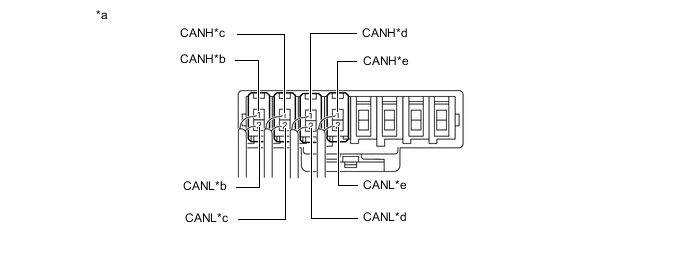
NO. 1 CAN JUNCTION CONNECTOR (for LHD)
-
Check the No. 1 CAN junction connector.
-
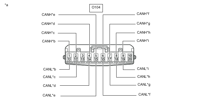
*a Front view of wire harness connector
(to No. 1 CAN Junction Connector)
*b to No. 2 CAN Junction Connector *c to Combination Meter Assembly *d to Central Gateway ECU (Network Gateway ECU) *e to Air Conditioning Amplifier Assembly *f to Torque Vectoring Differential ECU Assembly
(w/ Torque Vectoring Differential System)
*g to Certification ECU (Smart Key ECU Assembly) *h to Stereo Component Equalizer Assembly *i to Power Steering ECU Assembly - - Connection diagram
-
Check the connection diagram of the components which are connected to the No. 1 CAN junction connector.
Terminal No. (Symbol) Wiring Color Connected to O104-1 (CANH) L No. 2 CAN junction connector
(for Bus 2)
O104-11 (CANL) B O104-2 (CANH) LG Combination meter assembly
(for Bus 2)
O104-12 (CANL) B O104-4 (CANH) BE Central gateway ECU (network gateway ECU)
(for Bus 2)
O104-14 (CANL) B O104-5 (CANH) P Air conditioning amplifier assembly
(for Bus 2)
O104-15 (CANL) B O104-6 (CANH) P Torque vectoring differential ECU assembly*
(for Bus 2)
O104-16 (CANL) B O104-7 (CANH) W Certification ECU (smart key ECU assembly)
(for Bus 2)
O104-17 (CANL) B O104-8 (CANH) G Stereo component equalizer assembly
(for Bus 2)
O104-18 (CANL) B O104-9 (CANH) G Power steering ECU assembly
(for Bus 2)
O104-19 (CANL) B
-
*: w/ Torque Vectoring Differential System
-
-
-
-
NO. 2 CAN JUNCTION CONNECTOR (for LHD)
-
Check the No. 2 CAN junction connector.
-
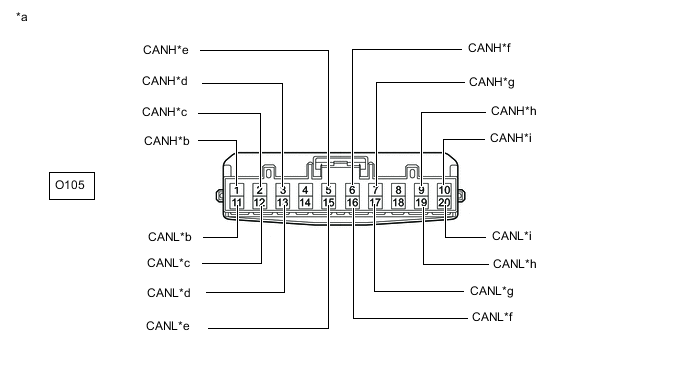
*a Front view of wire harness connector
(to No. 2 CAN Junction Connector)
*b to No. 1 CAN Junction Connector *c to Main Body ECU (Multiplex Network Body ECU) *d to ECM *e to Airbag ECU Assembly *f to Yaw Rate Sensor *g to Spoiler Control ECU Assembly *h to Steering Sensor *i to Skid Control ECU (Brake Actuator Assembly) - - Connection diagram
-
Check the connection diagram of the components which are connected to the No. 2 CAN junction connector.
Terminal No. (Symbol) Wiring Color Connected to O105-1 (CANH) L No. 1 CAN junction connector
(for Bus 2)
O105-11 (CANL) B O105-2 (CANH) Y Main body ECU (multiplex network body ECU)
(for Bus 2)
O105-12 (CANL) B O105-3 (CANH) R ECM
(for Bus 2)
O105-13 (CANL) B O105-5 (CANH) BE Airbag ECU assembly
(for Bus 2)
O105-15 (CANL) B O105-6 (CANH) G Yaw rate sensor
(for Bus 2)
O105-16 (CANL) B O105-7 (CANH) GR Spoiler control ECU assembly
(for Bus 2)
O105-17 (CANL) B O105-9 (CANH) P Steering sensor
(for Bus 2)
O105-19 (CANL) B O105-10 (CANH) SB Skid control ECU (brake actuator assembly)
(for Bus 2)
O105-20 (CANL) B
-
-
-
NO. 3 CAN JUNCTION CONNECTOR (for LHD)
-
Check the No. 3 CAN junction connector.
-
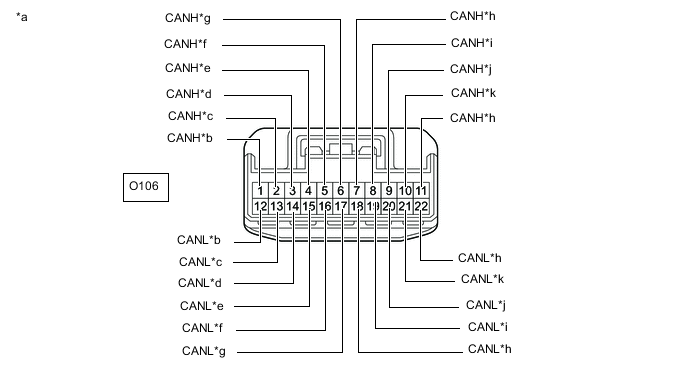
*a Front view of wire harness connector
(to No. 3 CAN Junction Connector)
*b to Multiplex Tilt and Telescopic ECU *c to No. 7 CAN Junction Connector *d to Main Body ECU (Multiplex Network Body ECU) *e to Outer Mirror Control ECU Assembly (for Driver side) *f to Headlight Light Control ECU Sub-assembly LH *g to Position Control ECU and Switch Assembly LH *h to Central Gateway ECU (Network Gateway ECU) *i to Telematics Transceiver
(w/ Telematics Transceiver)
*j to Radio Receiver Assembly *k to Option Connector (Bus Buffer ECU) - - Connection diagram
-
Check the connection diagram of the components which are connected to the No. 3 CAN junction connector.
Terminal No. (Symbol) Wiring Color Connected to O106-1 (CANH) G Multiplex tilt and telescopic ECU
(for Sub bus 1)
O106-12 (CANL) B O106-2 (CANH) LG No. 7 CAN junction connector
(for Sub bus 1)
O106-13 (CANL) B O106-3 (CANH) P Main body ECU (multiplex network body ECU)
(for Sub bus 1)
O106-14 (CANL) B O106-4 (CANH) W Outer mirror control ECU assembly (for driver side)
(for Sub bus 1)
O106-15 (CANL) B O106-5 (CANH) V Headlight light control ECU sub-assembly LH
(for Sub bus 1)
O106-16 (CANL) B O106-6 (CANH) R Position control ECU and switch assembly LH
(for Sub bus 1)
O106-17 (CANL) B O106-7 (CANH) R Central gateway ECU (network gateway ECU)
(for Bus 3)
O106-18 (CANL) B O106-8 (CANH) LG Telematics transceiver*
(for Bus 3)
O106-19 (CANL) B O106-9 (CANH) BE Radio receiver assembly
(for Bus 3)
O106-20 (CANL) B O106-10 (CANH) SB Option connector (bus buffer ECU)
(for Bus 3)
O106-21 (CANL) B O106-11 (CANH) V Central gateway ECU (network gateway ECU)
(for Bus 3)
O106-22 (CANL) B
-
*: w/ Telematics Transceiver
-
-
-
-
NO. 7 CAN JUNCTION CONNECTOR (for LHD)
-
Check the No. 7 CAN junction connector.
-
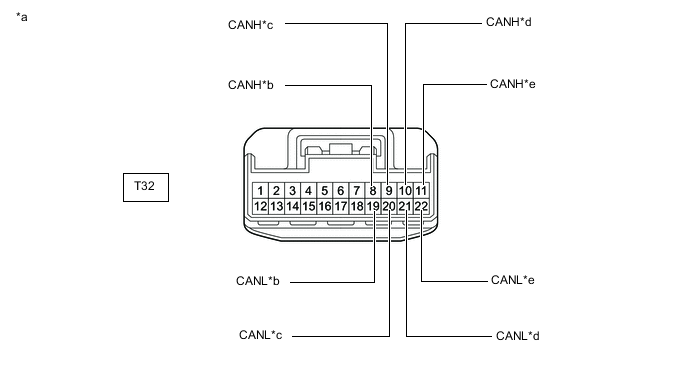
*a Front view of wire harness connector
(to No. 7 CAN Junction Connector)
*b to No. 3 CAN Junction Connector *c to Position Control ECU and Switch Assembly RH *d to Outer Mirror Control ECU Assembly (for Front Passenger Side) *e to No. 1 CAN Junction Terminal - - Connection diagram
-
Check the connection diagram of the components which are connected to the No. 7 CAN junction connector.
Terminal No. (Symbol) Wiring Color Connected to T32-8 (CANH) LG No. 3 CAN junction connector
(for Sub bus 1)
T32-19 (CANL) B T32-9 (CANH) R Position control ECU and switch assembly RH
(for Sub bus 1)
T32-20 (CANL) B T32-10 (CANH) W Outer mirror control ECU assembly (for front passenger side)
(for Sub bus 1)
T32-21 (CANL) B T32-11 (CANH) P No. 1 CAN junction terminal
(for Sub bus 1)
T32-22 (CANL) B
-
-
-
NO. 8 CAN JUNCTION CONNECTOR (for LHD)
-
Check the No. 8 CAN junction connector.
-

*a Front view of wire harness connector
(to No. 8 CAN Junction Connector)
*b to Torque Vectoring Differential ECU Assembly
(w/ Torque Vectoring Differential System)
*c to Skid Control ECU (Brake Actuator Assembly) *d to No. 10 CAN Junction Connector Connection diagram
-
Check the connection diagram of the components which are connected to the No. 8 CAN junction connector.
Terminal No. (Symbol) Wiring Color Connected to T44-2 (CANH) V Torque vectoring differential ECU assembly*
(for V3 bus)
T44-13 (CANL) B T44-3 (CANH) LG Skid control ECU (brake actuator assembly)
(for V3 bus)
T44-14 (CANL) B T44-4 (CANH) R No. 10 CAN junction connector
(for V3 bus)
T44-15 (CANL) B
-
*: w/ Torque Vectoring Differential System
-
-
-
-
NO. 10 CAN JUNCTION CONNECTOR (for LHD)
-
Check the No. 10 CAN junction connector.
-

*a Front view of wire harness connector
(to No. 10 CAN Junction Connector)
*b to No. 8 CAN Junction Connector *c to Roll Rate and Vertical Acceleration Sensor *d to ECM Connection diagram
-
Check the connection diagram of the components which are connected to the No. 10 CAN junction connector.
Terminal No. (Symbol) Wiring Color Connected to O169-1 (CANH) R No. 8 CAN junction connector
(for V3 bus)
O169-12 (CANL) B O169-2 (CANH) G Roll rate and vertical acceleration sensor
(for V3 bus)
O169-13 (CANL) B O169-3 (CANH) L ECM
(for V3 bus)
O169-14 (CANL) B
-
-
-
NO. 12 CAN JUNCTION CONNECTOR (for LHD)
-
Check the No. 12 CAN junction connector.
-

*a Front view of wire harness connector
(to No. 12 CAN Junction Connector)
*b to Rear Television Camera Assembly *c to No. 16 CAN Junction Connector *d to No. 2 CAN Junction Terminal *d to Blind Spot Monitor Sensor LH
(w/ Blind Spot Monitor System)
- - Connection diagram
-
Check the connection diagram of the components which are connected to the No. 9 CAN junction connector.
Terminal No. (Symbol) Wiring Color Connected to U57-2 (CANH) W Rear television camera assembly
(for Bus 5)
U57-8 (CANL) B U57-3 (CANH) BE No. 16 CAN junction connector
(for Bus 5)
U57-9 (CANL) B U57-4 (CANH) V No. 2 CAN junction terminal
(for Bus 5)
U57-10 (CANL) B U57-5 (CANH) R Blind spot monitor sensor LH*
(for Bus 5)
U57-11 (CANL) B
-
*: w/ Blind Spot Monitor System
-
-
-
-
NO. 13 CAN JUNCTION CONNECTOR (for LHD)
-
Check the No. 13 CAN junction connector.
Tip:Connectors that connect to the CAN junction connector can be distinguished by the color of their CAN bus lines. When the connectors have been disconnected from the CAN junction connector, reconnecting the connectors to non-original positions on the CAN junction connector does not affect system performance. However, it is preferred to reconnect the connectors to their original positions to avoid negative effects on the wiring such as tension on the wire harnesses, and to make future maintenance easier.
-
*a Component with harness connected
(No. 13 CAN Junction Connector)
*b to Central Gateway ECU (Network Gateway ECU) *c to No. 16 CAN Junction Connector *d to Absorber Control ECU *e to Driving Support ECU Assembly - - Connection diagram
-
Check the connection diagram of the components which are connected to the No. 13 CAN junction connector.
Terminal No. (Symbol) Wiring Color Connected to O152-1 (CANH) GR Central gateway ECU (network gateway ECU)
(for Bus 5)
O152-2 (CANL) B O153-1 (CANH) LG No. 16 CAN junction connector
(for Bus 5)
O153-2 (CANL) B O154-1 (CANH) SB Absorber control ECU
(for Bus 5)
O154-2 (CANL) B O155-1 (CANH) G Driving support ECU assembly
(for Bus 5)
O155-2 (CANL) B
-
-
-
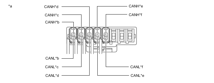
NO. 16 CAN JUNCTION CONNECTOR (for LHD)
-
Check the No. 16 CAN junction connector.
-
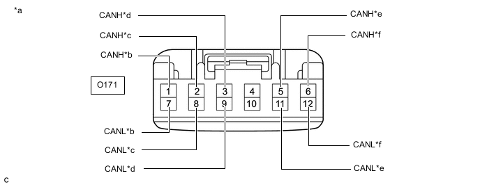
*a Front view of wire harness connector
(to No. 16 CAN Junction Connector)
*b to No. 13 CAN Junction Connector *c to Forward Recognition Camera *d to Millimeter Wave Radar Sensor Assembly *e to Clearance Warning ECU Assembly *f to No. 12 CAN Junction Connector Connection diagram
-
Check the connection diagram of the components which are connected to the No. 16 CAN junction connector.
Terminal No. (Symbol) Wiring Color Connected to O171-1 (CANH) LG No. 13 CAN junction connector
(for Bus 5)
O171-7 (CANL) B O171-2 (CANH) R Forward recognition camera
(for Bus 5)
O171-8 (CANL) B O171-3 (CANH) L Millimeter wave radar sensor assembly
(for Bus 5)
O171-9 (CANL) B O171-5 (CANH) P Clearance warning ECU assembly
(for Bus 5)
O171-11 (CANL) B O171-6 (CANH) BE No. 12 CAN junction connector
(for Bus 5)
O171-12 (CANL) B
-
-
-
NO. 1 CAN JUNCTION TERMINAL (for LHD)
-
Check the No. 1 CAN junction terminal.
-

*a Front view of wire harness connector
(to No. 1 CAN Junction Terminal)
*b to No. 7 CAN Junction Connector Connection diagram
-
Check the connection diagram of the components which are connected to the No. 1 CAN junction terminal.
Terminal No. (Symbol) Wiring Color Connected to O101-3 (CANH) P No. 7 CAN junction connector
(for Sub bus 1)
O101-2 (CANL) B
-
-
-
NO. 2 CAN JUNCTION TERMINAL (for LHD)
-
Check the No. 2 CAN junction terminal.
-

*a Front view of wire harness connector
(to No. 2 CAN Junction Terminal)
*b to No. 12 CAN Junction Connector Connection diagram
-
Check the connection diagram of the components which are connected to the No. 2 CAN junction terminal.
Terminal No. (Symbol) Wiring Color Connected to O102-3 (CANH) V No. 12 CAN junction connector
(for Bus 5)
O102-2 (CANL) B
-
-
-
NO. 1 CAN JUNCTION CONNECTOR (for RHD)
-
Check the No. 1 CAN junction connector.
-
*a Front view of wire harness connector
(to No. 1 CAN Junction Connector)
*b to No. 2 CAN Junction Connector *c to Combination Meter Assembly *d to Airbag ECU Assembly *e to Torque Vectoring Differential ECU Assembly
(w/ Torque Vectoring Differential System)
*f to Steering Sensor *g to Stereo Component Equalizer Assembly *h to Skid Control ECU (Brake Actuator Assembly) Connection diagram
-
Check the connection diagram of the components which are connected to the No. 1 CAN junction connector.
Terminal No. (Symbol) Wiring Color Connected to O104-1 (CANH) L No. 2 CAN junction connector
(for Bus 2)
O104-11 (CANL) B O104-2 (CANH) LG Combination meter assembly
(for Bus 2)
O104-12 (CANL) B O104-4 (CANH) BE Airbag ECU assembly
(for Bus 2)
O104-14 (CANL) B O104-6 (CANH) P Torque vectoring differential ECU assembly*
(for Bus 2)
O104-16 (CANL) B O104-7 (CANH) P Steering sensor
(for Bus 2)
O104-17 (CANL) B O104-8 (CANH) G Stereo component equalizer assembly
(for Bus 2)
O104-18 (CANL) B O104-9 (CANH) SB Skid control ECU (brake actuator assembly)
(for Bus 2)
O104-19 (CANL) B
-
*: w/ Torque Vectoring Differential System
-
-
-
-
NO. 2 CAN JUNCTION CONNECTOR (for RHD)
-
Check the No. 2 CAN junction connector.
-
*a Front view of wire harness connector
(to No. 2 CAN Junction Connector)
*b to No. 1 CAN Junction Connector *c to Main Body ECU (Multiplex Network Body ECU) *d to ECM *e to Central Gateway ECU (Network Gateway ECU) *f to Air Conditioning Amplifier Assembly *g to Yaw Rate Sensor *h to Certification ECU (Smart Key ECU Assembly) *i to Spoiler Control ECU Assembly *j to Power Steering ECU Assembly Connection diagram
-
Check the connection diagram of the components which are connected to the No. 2 CAN junction connector.
Terminal No. (Symbol) Wiring Color Connected to O105-1 (CANH) L No. 1 CAN junction connector
(for Bus 2)
O105-11 (CANL) B O105-2 (CANH) Y Main body ECU (multiplex network body ECU)
(for Bus 2)
O105-12 (CANL) B O105-3 (CANH) R ECM
(for Bus 2)
O105-13 (CANL) B O105-5 (CANH) BE Central gateway ECU (network gateway ECU)
(for Bus 2)
O105-15 (CANL) B O105-6 (CANH) P Air conditioning amplifier assembly
(for Bus 2)
O105-16 (CANL) B O105-7 (CANH) G Yaw rate sensor
(for Bus 2)
O105-17 (CANL) B O105-8 (CANH) W Certification ECU (smart key ECU assembly)
(for Bus 2)
O105-18 (CANL) B O105-9 (CANH) GR Spoiler control ECU assembly
(for Bus 2)
O105-19 (CANL) B O105-10 (CANH) G Power steering ECU assembly
(for Bus 2)
O105-20 (CANL) B
-
-
-
NO. 4 CAN JUNCTION CONNECTOR (for RHD)
-
Check the No. 4 CAN junction connector.
-
*a Front view of wire harness connector
(to No. 4 CAN Junction Connector)
*b to Multiplex Tilt and Telescopic ECU *c to No. 11 CAN Junction Connector *d to Main Body ECU (Multiplex Network Body ECU) *e to Outer Mirror Control ECU Assembly (for Front Passenger Side) *f to Headlight Light Control ECU Sub-assembly LH *g to Position Control ECU and Switch Assembly LH *h to Central Gateway ECU (Network Gateway ECU) *i to Radio Receiver Assembly - - Connection diagram
-
Check the connection diagram of the components which are connected to the No. 4 CAN junction connector.
Terminal No. (Symbol) Wiring Color Connected to O107-1 (CANH) G Multiplex tilt and telescopic ECU
(for Sub bus 1)
O107-12 (CANL) B O107-2 (CANH) LG No. 11 CAN junction connector
(for Sub Bus 1)
O107-13 (CANL) B O107-3 (CANH) P Main body ECU (multiplex network body ECU)
(for Sub bus 1)
O107-14 (CANL) B O107-4 (CANH) W Outer mirror control ECU assembly (for front passenger side)
(for Sub bus 1)
O107-15 (CANL) B O107-5 (CANH) V Headlight light control ECU sub-assembly LH
(for Sub bus 1)
O107-16 (CANL) B O107-6 (CANH) R Position control ECU and switch assembly LH
(for Sub bus 1)
O107-17 (CANL) B O107-7 (CANH) R Central gateway ECU (network gateway ECU)
(for Bus 3)
O107-18 (CANL) B O107-9 (CANH) BE Radio receiver assembly
(for Bus 3)
O107-20 (CANL) B O107-11 (CANH) V Central gateway ECU (network gateway ECU)
(for Bus 3)
O107-22 (CANL) B
-
-
-
NO. 6 CAN JUNCTION CONNECTOR (for RHD)
-
Check the No. 6 CAN junction connector.
-
*a Front view of wire harness connector
(to No. 6 CAN Junction Connector)
*b to No. 8 CAN Junction Connector *c to Roll Rate and Vertical Acceleration Sensor *d to ECM Connection diagram
-
Check the connection diagram of the components which are connected to the No. 6 CAN junction connector.
Terminal No. (Symbol) Wiring Color Connected to O110-1 (CANH) R No. 8 CAN junction connector
(for V3 bus)
O110-12 (CANL) B O110-2 (CANH) G Roll rate and vertical acceleration sensor
(for V3 bus)
O110-13 (CANL) B O110-3 (CANH) L ECM
(for V3 bus)
O110-14 (CANL) B
-
-
-
NO. 8 CAN JUNCTION CONNECTOR (for RHD)
-
Check the No. 8 CAN junction connector.
-
*a Front view of wire harness connector
(to No. 8 CAN Junction Connector)
*b to Torque Vectoring Differential ECU Assembly
(w/ Torque Vectoring Differential System)
*c to Skid Control ECU (Brake Actuator Assembly) *d to No. 6 CAN Junction Connector Connection diagram
-
Check the connection diagram of the components which are connected to the No. 8 CAN junction connector.
Terminal No. (Symbol) Wiring Color Connected to T44-2 (CANH) V Torque vectoring differential ECU assembly*
(for V3 bus)
T44-13 (CANL) B T44-3 (CANH) LG Skid control ECU (brake actuator assembly)
(for V3 bus)
T44-14 (CANL) B T44-4 (CANH) R No. 6 CAN junction connector
(for V3 bus)
T44-15 (CANL) B
-
*: w/ Torque Vectoring Differential System
-
-
-
-
NO. 11 CAN JUNCTION CONNECTOR (for RHD)
-
Check the No. 11 CAN junction connector.
-

*a Front view of wire harness connector
(to No. 11 CAN Junction Connector)
*b to No. 4 CAN Junction Connector *c to Position Control ECU and Switch Assembly RH *d to Outer Mirror Control ECU Assembly (for Driver Side) *e to No. 1 CAN Junction Terminal - - Connection diagram
-
Check the connection diagram of the components which are connected to the No. 11 CAN junction connector.
Terminal No. (Symbol) Wiring Color Connected to T50-8 (CANH) LG No. 4 CAN junction connector
(for Sub bus 1)
T50-19 (CANL) B T50-9 (CANH) R Position control ECU and switch assembly RH
(for Sub bus 1)
T50-20 (CANL) B T50-10 (CANH) W Outer mirror control ECU assembly (for driver side)
(for Sub bus 1)
T50-21 (CANL) B T50-11 (CANH) P No. 1 CAN junction terminal
(for Sub bus 1)
T50-22 (CANL) B
-
-
-
NO. 12 CAN JUNCTION CONNECTOR (for RHD)
-
Check the No. 12 CAN junction connector.
-
*a Front view of wire harness connector
(to No. 12 CAN Junction Connector)
*b to Rear Television Camera Assembly *c to No. 14 CAN Junction Connector *d to No. 2 CAN Junction Terminal *d to Blind Spot Monitor Sensor LH
(w/ Blind Spot Monitor System)
- - Connection diagram
-
Check the connection diagram of the components which are connected to the No. 5 CAN junction connector.
Terminal No. (Symbol) Wiring Color Connected to U57-2 (CANH) W Rear television camera assembly
(for Bus 5)
U57-8 (CANL) B U57-3 (CANH) BE No. 14 CAN junction connector
(for Bus 5)
U57-9 (CANL) B U57-4 (CANH) V No. 2 CAN junction terminal
(for Bus 5)
U57-10 (CANL) B U57-5 (CANH) R Blind spot monitor sensor LH*
(for Bus 5)
U57-11 (CANL) B
-
*: w/ Blind Spot Monitor System
-
-
-
-
NO. 14 CAN JUNCTION CONNECTOR (for RHD)
-
Check the No. 14 CAN junction connector.
Tip:Connectors that connect to the CAN junction connector can be distinguished by the color of their CAN bus lines. When the connectors have been disconnected from the CAN junction connector, reconnecting the connectors to non-original positions on the CAN junction connector does not affect system performance. However, it is preferred to reconnect the connectors to their original positions to avoid negative effects on the wiring such as tension on the wire harnesses, and to make future maintenance easier.
-
*a Component with harness connected
(No. 14 CAN Junction Connector)
*b to No. 15 CAN Junction Connector *c to Forward Recognition Camera *d to Millimeter Wave Radar Sensor Assembly *e to Clearance Warning ECU Assembly *f to No. 12 CAN Junction Connector Connection diagram
-
Check the connection diagram of the components which are connected to the No. 14 CAN junction connector.
Terminal No. (Symbol) Wiring Color Connected to O156-1 (CANH) LG No. 15 CAN junction connector
(for Bus 5)
O156-2 (CANL) B O157-1 (CANH) R Forward recognition camera
(for Bus 5)
O157-2 (CANL) B O158-1 (CANH) L Millimeter wave radar sensor assembly
(for Bus 5)
O158-2 (CANL) B O159-1 (CANH) P Clearance warning ECU assembly
(for Bus 5)
O159-2 (CANL) B O160-1 (CANH) BE No. 12 CAN junction connector
(for Bus 5)
O160-2 (CANL) B
-
-
-
NO. 15 CAN JUNCTION CONNECTOR (for RHD)
-
Check the No. 15 CAN junction connector.
-
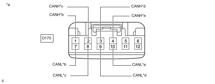
*a Front view of wire harness connector
(to No. 15 CAN Junction Connector)
*b to Absorber Control ECU *c to Driving Support ECU Assembly *d to Central Gateway ECU (Network Gateway ECU) *e to No. 14 CAN Junction Connector - - Connection diagram
-
Check the connection diagram of the components which are connected to the No. 15 CAN junction connector.
Terminal No. (Symbol) Wiring Color Connected to O170-1 (CANH) SB Absorber control ECU
(for Bus 5)
O170-7 (CANL) B O170-2 (CANH) G Driving support ECU assembly
(for Bus 5)
O170-8 (CANL) B O170-3 (CANH) GR Central gateway ECU (network gateway ECU)
(for Bus 5)
O170-9 (CANL) B O170-4 (CANH) LG No. 14 CAN junction connector
(for Bus 5)
O170-10 (CANL) B
-
-
-
NO. 1 CAN JUNCTION TERMINAL (for RHD)
-
Check the No. 1 CAN junction terminal.
-
*a Front view of wire harness connector
(to No. 1 CAN Junction Terminal)
*b to No. 11 CAN Junction Connector Connection diagram
-
Check the connection diagram of the components which are connected to the No. 1 CAN junction terminal.
Terminal No. (Symbol) Wiring Color Connected to O101-3 (CANH) P No. 11 CAN junction connector
(for Sub bus 1)
O101-2 (CANL) B
-
-
-
NO. 2 CAN JUNCTION TERMINAL (for RHD)
-
Check the No. 2 CAN junction terminal.
-
*a Front view of wire harness connector
(to No. 2 CAN Junction Terminal)
*b to No. 12 CAN Junction Connector Connection diagram
-
Check the connection diagram of the components which are connected to the No. 2 CAN junction terminal.
Terminal No. (Symbol) Wiring Color Connected to O102-3 (CANH) V No. 12 CAN junction connector
(for Bus 5)
O102-2 (CANL) B
-
-
-
DLC3
-
Disconnect the cable from the negative (-) battery terminal.
-
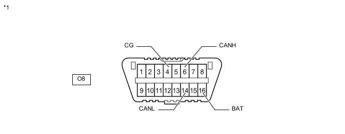
*1 DLC3 - - Measure the resistance according to the value(s) in the table below.
Standard Resistance Terminal No. (Symbol) Wiring Color Terminal Description Condition Specified Condition O8-6 (CANH) - O8-14 (CANL) W - B HIGH-level CAN bus line - LOW-level CAN bus line Cable disconnected from negative (-) battery terminal 54 to 69 Ω O8-6 (CANH) - O8-4 (CG) W - W-B HIGH-level CAN bus line - Ground Cable disconnected from negative (-) battery terminal 200 Ω or higher O8-14 (CANL) - O8-4 (CG) B - W-B LOW-level CAN bus line - Ground Cable disconnected from negative (-) battery terminal 200 Ω or higher O8-6 (CANH) - O8-16 (BAT) W - L HIGH-level CAN bus line - Battery positive (+) Cable disconnected from negative (-) battery terminal 6 kΩ or higher O8-14 (CANL) - O8-16 (BAT) B - L LOW-level CAN bus line - Battery positive (+) Cable disconnected from negative (-) battery terminal 6 kΩ or higher
-
-
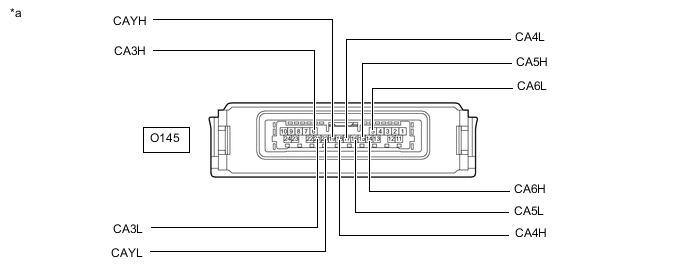
*a Component without harness connected
(Central Gateway ECU (Network Gateway ECU))
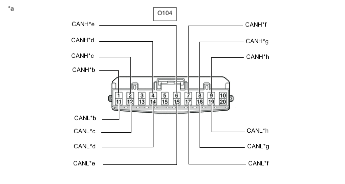
- - CENTRAL GATEWAY ECU (NETWORK GATEWAY ECU)
-
Disconnect the cable from the negative (-) battery terminal.
-
Disconnect the O145 central gateway ECU (network gateway ECU) connector.
-
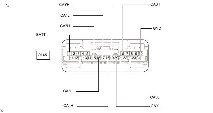
*a Front view of wire harness connector
(to Central Gateway ECU (Network Gateway ECU))
- - Measure the resistance according to the value(s) in the table below.
Standard Resistance Table 1. Bus 2 Branch Lines Terminal No. (Symbol) Wiring Color Terminal Description Condition Specified Condition O145-18 (CA4H) - O145-17 (CA4L) BE - B HIGH-level CAN bus line - LOW-level CAN bus line Cable disconnected from negative (-) battery terminal 54 to 69 Ω O145-18 (CA4H) - O145-10 (GND) BE - BR HIGH-level CAN bus line - Ground Cable disconnected from negative (-) battery terminal 200 Ω or higher O145-17 (CA4L) - O145-10 (GND) B - BR LOW-level CAN bus line - Ground Cable disconnected from negative (-) battery terminal 200 Ω or higher O145-18 (CA4H) - O145-1 (BATT) BE - LG HIGH-level CAN bus line - Battery positive (+) Cable disconnected from negative (-) battery terminal 6 kΩ or higher O145-17 (CA4L) - O145-1 (BATT) B - LG LOW-level CAN bus line - Battery positive (+) Cable disconnected from negative (-) battery terminal 6 kΩ or higher Table 2. Bus 3 Main Lines Terminal No. (Symbol) Wiring Color Terminal Description Condition Specified Condition O145-6 (CA3H) - O145-19 (CAYH) V - R HIGH-level CAN bus line - HIGH-level CAN bus line Cable disconnected from negative (-) battery terminal Below 1 Ω O145-21 (CA3L) - O145-20 (CAYL) B - B LOW-level CAN bus line - LOW-level CAN bus line Cable disconnected from negative (-) battery terminal Below 1 Ω O145-6 (CA3H) - O145-10 (GND) V - BR HIGH-level CAN bus line - Ground Cable disconnected from negative (-) battery terminal 200 Ω or higher O145-21 (CA3L) - O145-10 (GND) B - BR LOW-level CAN bus line - Ground Cable disconnected from negative (-) battery terminal 200 Ω or higher O145-6 (CA3H) - O145-1 (BATT) V - LG HIGH-level CAN bus line - Battery positive (+) Cable disconnected from negative (-) battery terminal 6 kΩ or higher O145-21 (CA3L) - O145-1 (BATT) B - LG LOW-level CAN bus line - Battery positive (+) Cable disconnected from negative (-) battery terminal 6 kΩ or higher Table 3. Bus 5 Main Lines Terminal No. (Symbol) Wiring Color Terminal Description Condition Specified Condition O145-15 (CA5H) - O145-16 (CA5L) GR - B HIGH-level CAN bus line - LOW-level CAN bus line Cable disconnected from negative (-) battery terminal 108 to 132 Ω O145-15 (CA5H) - O145-10 (GND) GR - BR HIGH-level CAN bus line - Ground Cable disconnected from negative (-) battery terminal 200 Ω or higher O145-16 (CA5L) - O145-10 (GND) B - BR LOW-level CAN bus line - Ground Cable disconnected from negative (-) battery terminal 200 Ω or higher O145-15 (CA5H) - O145-1 (BATT) GR - LG HIGH-level CAN bus line - Battery positive (+) Cable disconnected from negative (-) battery terminal 6 kΩ or higher O145-16 (CA5L) - O145-1 (BATT) B - LG LOW-level CAN bus line - Battery positive (+) Cable disconnected from negative (-) battery terminal 6 kΩ or higher
-
-
ECM
Refer to Terminals of ECU.
-
w/ Canister Pump Module
-
w/o Canister Pump Module
-
Disconnect the cable from the negative (-) battery terminal.
-
Disconnect the A78 ECM connector.
-
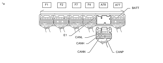
*a Rear view of wire harness connector
(to ECM)
- - Measure the resistance according to the value(s) in the table below.
Standard Resistance Table 4. Bus 2 Main Lines Terminal No. (Symbol) Wiring Color Terminal Description Condition Specified Condition A78-13 (CANH) - A78-14 (CANL) R - B HIGH-level CAN bus line - LOW-level CAN bus line Cable disconnected from negative (-) battery terminal 108 to 132 Ω A78-13 (CANH) - F4-1 (E1) R - W-B HIGH-level CAN bus line - Ground Cable disconnected from negative (-) battery terminal 200 Ω or higher A78-14 (CANL) - F4-1 (E1) B - W-B LOW-level CAN bus line - Ground Cable disconnected from negative (-) battery terminal 200 Ω or higher A78-13 (CANH) - A77-5 (BATT) R - L HIGH-level CAN bus line - Battery positive (+) Cable disconnected from negative (-) battery terminal 6 kΩ or higher A78-14 (CANL) - A77-5 (BATT) B - L LOW-level CAN bus line - Battery positive (+) Cable disconnected from negative (-) battery terminal 6 kΩ or higher Table 5. V3 Bus Main Lines Terminal No. (Symbol) Wiring Color Terminal Description Condition Specified Condition A78-11 (CANP) - A78-12 (CANN) L - B HIGH-level CAN bus line - LOW-level CAN bus line Cable disconnected from negative (-) battery terminal 108 to 132 Ω A78-11 (CANP) - F4-1 (E1) L - W-B HIGH-level CAN bus line - Ground Cable disconnected from negative (-) battery terminal 200 Ω or higher A78-12 (CANN) - F4-1 (E1) B - W-B LOW-level CAN bus line - Ground Cable disconnected from negative (-) battery terminal 200 Ω or higher A78-11 (CANP) - A77-5 (BATT) L - L HIGH-level CAN bus line - Battery positive (+) Cable disconnected from negative (-) battery terminal 6 kΩ or higher A78-12 (CANN) - A77-5 (BATT) B - L LOW-level CAN bus line - Battery positive (+) Cable disconnected from negative (-) battery terminal 6 kΩ or higher
-
-
COMBINATION METER ASSEMBLY
Refer to Terminals of ECU.
-
Disconnect the cable from the negative (-) battery terminal.
-
Disconnect the O3 combination meter assembly connector.
-

*a Front view of wire harness connector
(to Combination Meter Assembly)
- - Measure the resistance according to the value(s) in the table below.
Standard Resistance Terminal No. (Symbol) Wiring Color Terminal Description Condition Specified Condition O3-29 (CANH) - O3-30 (CANL) LG - B HIGH-level CAN bus line - LOW-level CAN bus line Cable disconnected from negative (-) battery terminal 108 to 132 Ω O3-29 (CANH) - O3-31 (ES) LG - BR HIGH-level CAN bus line - Ground Cable disconnected from negative (-) battery terminal 200 Ω or higher O3-30 (CANL) - O3-31 (ES) B - BR LOW-level CAN bus line - Ground Cable disconnected from negative (-) battery terminal 200 Ω or higher O3-29 (CANH) - O3-22 (B) LG - LG HIGH-level CAN bus line - Battery positive (+) Cable disconnected from negative (-) battery terminal 6 kΩ or higher O3-30 (CANL) - O3-22 (B) B - LG LOW-level CAN bus line - Battery positive (+) Cable disconnected from negative (-) battery terminal 6 kΩ or higher
-
-
INSTRUMENT PANEL JUNCTION BLOCK ASSEMBLY AND MAIN BODY ECU (MULTIPLEX NETWORK BODY ECU)
Refer to Terminals of ECU.
-
Disconnect the cable from the negative (-) battery terminal.
-
Disconnect the O1 and O2 main body ECU (multiplex network body ECU) connectors.
-
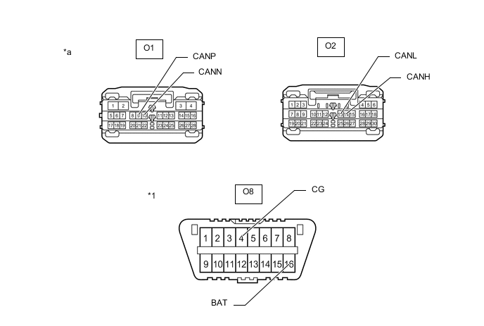
*1 DLC3 - - *a Front view of wire harness connector
(to Main Body ECU (Multiplex Network Body ECU))
- - Measure the resistance according to the value(s) in the table below.
Standard Resistance Table 6. Bus 2 Branch Lines Terminal No. (Symbol) Wiring Color Terminal Description Condition Specified Condition O2-14 (CANH) - O2-13 (CANL) Y - B HIGH-level CAN bus line - LOW-level CAN bus line Cable disconnected from negative (-) battery terminal 54 to 69 Ω O2-14 (CANH) - O8-4 (CG) Y - W-B HIGH-level CAN bus line - Ground Cable disconnected from negative (-) battery terminal 200 Ω or higher O2-13 (CANL) - O8-4 (CG) B - W-B LOW-level CAN bus line - Ground Cable disconnected from negative (-) battery terminal 200 Ω or higher O2-14 (CANH) - O8-16 (BAT) Y - L HIGH-level CAN bus line - Battery positive (+) Cable disconnected from negative (-) battery terminal 6 kΩ or higher O2-13 (CANL) - O8-16 (BAT) B - L LOW-level CAN bus line - Battery positive (+) Cable disconnected from negative (-) battery terminal 6 kΩ or higher Table 7. Sub Bus 1 Main Lines Terminal No. (Symbol) Wiring Color Terminal Description Condition Specified Condition O1-9 (CANP) - O1-10 (CANN) P - B HIGH-level CAN bus line - LOW-level CAN bus line Cable disconnected from negative (-) battery terminal 108 to 132 Ω O1-9 (CANP) - O8-4 (CG) P - W-B HIGH-level CAN bus line - Ground Cable disconnected from negative (-) battery terminal 200 Ω or higher O1-10 (CANN) - O8-4 (CG) B - W-B LOW-level CAN bus line - Ground Cable disconnected from negative (-) battery terminal 200 Ω or higher O1-9 (CANP) - O8-16 (BAT) P - L HIGH-level CAN bus line - Battery positive (+) Cable disconnected from negative (-) battery terminal 6 kΩ or higher O1-10 (CANN) - O8-16 (BAT) B - L LOW-level CAN bus line - Battery positive (+) Cable disconnected from negative (-) battery terminal 6 kΩ or higher
-
-
SKID CONTROL ECU (BRAKE ACTUATOR ASSEMBLY)
Refer to Terminals of ECU.
-
Disconnect the cable from the negative (-) battery terminal.
-
Disconnect the A86 skid control ECU (brake actuator assembly) connector.
-
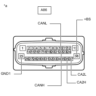
*a Front view of wire harness connector
(to Skid Control ECU (Brake Actuator Assembly))
Measure the resistance according to the value(s) in the table below.
Standard Resistance Table 8. Bus 2 Branch Lines Terminal No. (Symbol) Wiring Color Terminal Description Condition Specified Condition A86-22 (CANH) - A86-10 (CANL) SB - B HIGH-level CAN bus line - LOW-level CAN bus line Cable disconnected from negative (-) battery terminal 54 to 69 Ω A86-22 (CANH) - A86-25 (GND1) SB - W HIGH-level CAN bus line - Ground Cable disconnected from negative (-) battery terminal 200 Ω or higher A86-10 (CANL) - A86-25 (GND1) B - W LOW-level CAN bus line - Ground Cable disconnected from negative (-) battery terminal 200 Ω or higher A86-22 (CANH) - A86-38 (+BS) SB - W HIGH-level CAN bus line - Battery positive (+) Cable disconnected from negative (-) battery terminal 6 kΩ or higher A86-10 (CANL) - A86-38 (+BS) B - W LOW-level CAN bus line - Battery positive (+) Cable disconnected from negative (-) battery terminal 6 kΩ or higher Table 9. V3 Bus Main Lines Terminal No. (Symbol) Wiring Color Terminal Description Condition Specified Condition A86-36 (CA2H) - A86-37 (CA2L) LG - B HIGH-level CAN bus line - LOW-level CAN bus line Cable disconnected from negative (-) battery terminal 108 to 132 Ω A86-36 (CA2H) - A86-25 (GND1) LG - W HIGH-level CAN bus line - Ground Cable disconnected from negative (-) battery terminal 200 Ω or higher A86-37 (CA2L) - A86-25 (GND1) B - W LOW-level CAN bus line - Ground Cable disconnected from negative (-) battery terminal 200 Ω or higher A86-36 (CA2H) - A86-38 (+BS) LG - W HIGH-level CAN bus line - Battery positive (+) Cable disconnected from negative (-) battery terminal 6 kΩ or higher A86-37 (CA2L) - A86-38 (+BS) B - W LOW-level CAN bus line - Battery positive (+) Cable disconnected from negative (-) battery terminal 6 kΩ or higher
-
-
*a Component without harness connected
(Steering Sensor)
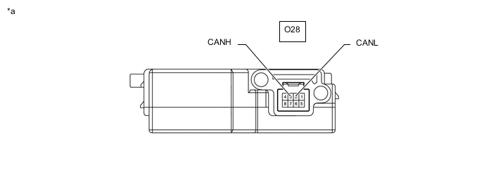
- - STEERING SENSOR
-
Disconnect the cable from the negative (-) battery terminal.
-
Disconnect the O28 steering sensor connector.
-

*a Front view of wire harness connector
(to Steering Sensor)
- - Measure the resistance according to the value(s) in the table below.
Standard Resistance Terminal No. (Symbol) Wiring Color Terminal Description Condition Specified Condition O28-3 (CANH) - O28-2 (CANL) P - B HIGH-level CAN bus line - LOW-level CAN bus line Cable disconnected from negative (-) battery terminal 54 to 69 Ω O28-3 (CANH) - O28-1 (ESS) P - BR HIGH-level CAN bus line - Ground Cable disconnected from negative (-) battery terminal 200 Ω or higher O28-2 (CANL) - O28-1 (ESS) B - BR LOW-level CAN bus line - Ground Cable disconnected from negative (-) battery terminal 200 Ω or higher O28-3 (CANH) - O28-8 (BAT) P - LG HIGH-level CAN bus line - Battery positive (+) Cable disconnected from negative (-) battery terminal 6 kΩ or higher O28-2 (CANL) - O28-8 (BAT) B - LG LOW-level CAN bus line - Battery positive (+) Cable disconnected from negative (-) battery terminal 6 kΩ or higher
-
-

*a Component without harness connected
(Yaw Rate Sensor)
- - YAW RATE SENSOR
-
Disconnect the cable from the negative (-) battery terminal.
-
Disconnect the O81 yaw rate sensor connector.
-

*a Front view of wire harness connector
(to Yaw Rate Sensor)
- - Measure the resistance according to the value(s) in the table below.
Standard Resistance Terminal No. (Symbol) Wiring Color Terminal Description Condition Specified Condition O81-3 (CANH) - O81-2 (CANL) G - B HIGH-level CAN bus line - LOW-level CAN bus line Cable disconnected from negative (-) battery terminal 54 to 69 Ω O81-3 (CANH) - O81-1 (GND) G - BR HIGH-level CAN bus line - Ground Cable disconnected from negative (-) battery terminal 200 Ω or higher O81-2 (CANL) - O81-1 (GND) B - BR LOW-level CAN bus line - Ground Cable disconnected from negative (-) battery terminal 200 Ω or higher O81-3 (CANH) - O81-6 (+B) G - LG HIGH-level CAN bus line - Battery positive (+) Cable disconnected from negative (-) battery terminal 6 kΩ or higher O81-2 (CANL) - O81-6 (+B) B - LG LOW-level CAN bus line - Battery positive (+) Cable disconnected from negative (-) battery terminal 6 kΩ or higher
-
-
POWER STEERING ECU ASSEMBLY
Refer to Terminals of ECU.
-
Disconnect the cable from the negative (-) battery terminal.
-
Disconnect the A18 power steering ECU assembly connector.
-

*a Front view of wire harness connector
(to Power Steering ECU Assembly)
- - Measure the resistance according to the value(s) in the table below.
Standard Resistance Terminal No. (Symbol) Wiring Color Terminal Description Condition Specified Condition A18-3 (CA1H) - A18-2 (CA1L) G - B HIGH-level CAN bus line - LOW-level CAN bus line Cable disconnected from negative (-) battery terminal 54 to 69 Ω A18-3 (CA1H) - A18-9 (PGND) G - B HIGH-level CAN bus line - Ground Cable disconnected from negative (-) battery terminal 200 Ω or higher A18-2 (CA1L) - A18-9 (PGND) B - B LOW-level CAN bus line - Ground Cable disconnected from negative (-) battery terminal 200 Ω or higher A18-3 (CA1H) - A18-10 (PIG) G - B HIGH-level CAN bus line - Battery positive (+) Cable disconnected from negative (-) battery terminal 6 kΩ or higher A18-2 (CA1L) - A18-10 (PIG) B - B LOW-level CAN bus line - Battery positive (+) Cable disconnected from negative (-) battery terminal 6 kΩ or higher
-
-
AIRBAG ECU ASSEMBLY
Refer to Terminals of ECU.
-
Disconnect the cable from the negative (-) battery terminal.
-
Disconnect the O50 airbag ECU assembly connector.
-
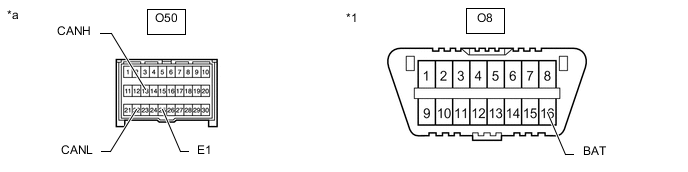
*1 DLC3 - - *a Front view of wire harness connector
(to Airbag ECU Assembly)
- - Measure the resistance according to the value(s) in the table below.
Standard Resistance Terminal No. (Symbol) Wiring Color Terminal Description Condition Specified Condition O50-13 (CANH) - O50-22 (CANL) BE - B HIGH-level CAN bus line - LOW-level CAN bus line Cable disconnected from negative (-) battery terminal 54 to 69 Ω O50-13 (CANH) - O50-25 (E1) BE - BR HIGH-level CAN bus line - Ground Cable disconnected from negative (-) battery terminal 200 Ω or higher O50-22 (CANL) - O50-25 (E1) B - BR LOW-level CAN bus line - Ground Cable disconnected from negative (-) battery terminal 200 Ω or higher O50-13 (CANH) - O8-16 (BAT) BE - L HIGH-level CAN bus line - Battery positive (+) Cable disconnected from negative (-) battery terminal 6 kΩ or higher O50-22 (CANL) - O8-16 (BAT) B - L LOW-level CAN bus line - Battery positive (+) Cable disconnected from negative (-) battery terminal 6 kΩ or higher
-
-
CERTIFICATION ECU (SMART KEY ECU ASSEMBLY)
Refer to Terminals of ECU.
-
Disconnect the cable from the negative (-) battery terminal.
-
Disconnect the O6 certification ECU (smart key ECU assembly) connector.
-

*a Front view of wire harness connector
(to Certification ECU (Smart Key ECU Assembly))
- - Measure the resistance according to the value(s) in the table below.
Standard Resistance Terminal No. (Symbol) Wiring Color Terminal Description Condition Specified Condition O6-7 (CANH) - O6-8 (CANL) W - B HIGH-level CAN bus line - LOW-level CAN bus line Cable disconnected from negative (-) battery terminal 54 to 69 Ω O6-7 (CANH) - O6-11 (E) W - BR HIGH-level CAN bus line - Ground Cable disconnected from negative (-) battery terminal 200 Ω or higher O6-8 (CANL) - O6-11 (E) B - BR LOW-level CAN bus line - Ground Cable disconnected from negative (-) battery terminal 200 Ω or higher O6-7 (CANH) - O6-10 (+B) W - BE HIGH-level CAN bus line - Battery positive (+) Cable disconnected from negative (-) battery terminal 6 kΩ or higher O6-8 (CANL) - O6-10 (+B) B - BE LOW-level CAN bus line - Battery positive (+) Cable disconnected from negative (-) battery terminal 6 kΩ or higher
-
-
RADIO RECEIVER ASSEMBLY
Refer to Terminals of ECU.
-
w/ Audio and Visual System (for 10.3 Inch Display)
-
w/ Audio and Visual System (for 7 Inch Display)
-
w/ Navigation System
-
Disconnect the cable from the negative (-) battery terminal.
-
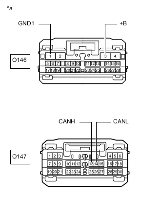
*a Front view of wire harness connector
(to Radio Receiver Assembly)
Disconnect the O146 and O147 radio receiver assembly connectors.
-
Measure the resistance according to the value(s) in the table below.
Standard Resistance Terminal No. (Symbol) Wiring Color Terminal Description Condition Specified Condition O147-13 (CANH) - O147-14 (CANL) BE - B HIGH-level CAN bus line - LOW-level CAN bus line Cable disconnected from negative (-) battery terminal 54 to 69 Ω O147-13 (CANH) - O146-1 (GND1) BE - W-B HIGH-level CAN bus line - Ground Cable disconnected from negative (-) battery terminal 200 Ω or higher O147-14 (CANL) - O146-1 (GND1) B - W-B LOW-level CAN bus line - Ground Cable disconnected from negative (-) battery terminal 200 Ω or higher O147-13 (CANH) - O146-3 (+B) BE - V HIGH-level CAN bus line - Battery positive (+) Cable disconnected from negative (-) battery terminal 6 kΩ or higher O147-14 (CANL) - O146-3 (+B) B - V LOW-level CAN bus line - Battery positive (+) Cable disconnected from negative (-) battery terminal 6 kΩ or higher
-
-
AIR CONDITIONING AMPLIFIER ASSEMBLY
Refer to Terminals of ECU.
-
Disconnect the cable from the negative (-) battery terminal.
-
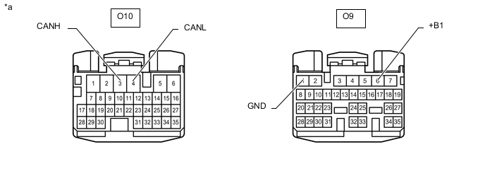
*a Front view of wire harness connector
(to Air Conditioning Amplifier Assembly)
- - Disconnect the O9 and O10 air conditioning amplifier assembly connectors.
-
Measure the resistance according to the value(s) in the table below.
Standard Resistance Terminal No. (Symbol) Wiring Color Terminal Description Condition Specified Condition O10-3 (CANH) - O10-4 (CANL) P - B HIGH-level CAN bus line - LOW-level CAN bus line Cable disconnected from negative (-) battery terminal 54 to 69 Ω O10-3 (CANH) - O9-1 (GND) P - BR HIGH-level CAN bus line - Ground Cable disconnected from negative (-) battery terminal 200 Ω or higher O10-4 (CANL) - O9-1 (GND) B - BR LOW-level CAN bus line - Ground Cable disconnected from negative (-) battery terminal 200 Ω or higher O10-3 (CANH) - O9-6 (+B1) P - L HIGH-level CAN bus line - Battery positive (+) Cable disconnected from negative (-) battery terminal 6 kΩ or higher O10-4 (CANL) - O9-6 (+B1) B - L LOW-level CAN bus line - Battery positive (+) Cable disconnected from negative (-) battery terminal 6 kΩ or higher
-
-
TELEMATICS TRANSCEIVER (w/ Telematics Transceiver)
Refer to Terminals of ECU.
-
Disconnect the cable from the negative (-) battery terminal.
-
Disconnect the O65 telematics transceiver connector.
-

*a Front view of wire harness connector
(to Telematics Transceiver)
- - Measure the resistance according to the value(s) in the table below.
Standard Resistance Terminal No. (Symbol) Wiring Color Terminal Description Condition Specified Condition O65-15 (CANP) - O65-16 (CANN) SB - B HIGH-level CAN bus line - LOW-level CAN bus line Cable disconnected from negative (-) battery terminal 54 to 69 Ω O65-15 (CANP) - O65-4 (E) SB - BR HIGH-level CAN bus line - Ground Cable disconnected from negative (-) battery terminal 200 Ω or higher O65-16 (CANN) - O65-4 (E) B - BR LOW-level CAN bus line - Ground Cable disconnected from negative (-) battery terminal 200 Ω or higher O65-15 (CANP) - O65-1 (+B) SB - P HIGH-level CAN bus line - Battery positive (+) Cable disconnected from negative (-) battery terminal 6 kΩ or higher O65-16 (CANN) - O65-1 (+B) B - P LOW-level CAN bus line - Battery positive (+) Cable disconnected from negative (-) battery terminal 6 kΩ or higher
-
-
HEADLIGHT LIGHT CONTROL ECU SUB-ASSEMBLY LH
Refer to Terminals of ECU.
-
Disconnect the cable from the negative (-) battery terminal.
-
Disconnect the A3 headlight light control ECU sub-assembly LH connector.
-
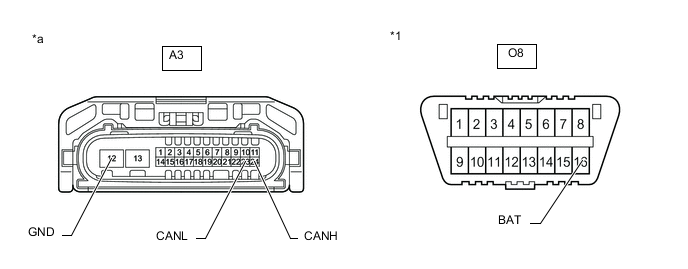
*1 DLC3 - - *a Front view of wire harness connector
(to Headlight Light Control ECU Sub-assembly LH)
- - Measure the resistance according to the value(s) in the table below.
Standard Resistance Terminal No. (Symbol) Wiring Color Terminal Description Condition Specified Condition A3-24 (CANH) - A3-23 (CANL) V - B HIGH-level CAN bus line - LOW-level CAN bus line Cable disconnected from negative (-) battery terminal 54 to 69 Ω A3-24 (CANH) - A3-12 (GND) V - W-B HIGH-level CAN bus line - Ground Cable disconnected from negative (-) battery terminal 200 Ω or higher A3-23 (CANL) - A3-12 (GND) B - W-B LOW-level CAN bus line - Ground Cable disconnected from negative (-) battery terminal 200 Ω or higher A3-24 (CANH) - O8-16 (BAT) V - L HIGH-level CAN bus line - Battery positive (+) Cable disconnected from negative (-) battery terminal 6 kΩ or higher A3-23 (CANL) - O8-16 (BAT) B - L LOW-level CAN bus line - Battery positive (+) Cable disconnected from negative (-) battery terminal 6 kΩ or higher
-
-
OUTER MIRROR CONTROL ECU ASSEMBLY
Refer to Terminals of ECU.
-
Disconnect the cable from the negative (-) battery terminal.
-

*a Front view of wire harness connector
(to Outer Mirror Control ECU Assembly (for Driver Side)) (for LHD)
(to Outer Mirror Control ECU Assembly (for Front Passenger Side)) (for RHD)
- - Disconnect the S12 outer mirror control ECU assembly connector.
-
Measure the resistance according to the value(s) in the table below.
Standard Resistance Terminal No. (Symbol) Wiring Color Terminal Description Condition Specified Condition S12-9 (CANP) - S12-8 (CANN) W - B HIGH-level CAN bus line - LOW-level CAN bus line Cable disconnected from negative (-) battery terminal 54 to 69 Ω S12-9 (CANP) - S12-7 (GND) W - W-B HIGH-level CAN bus line - Ground Cable disconnected from negative (-) battery terminal 200 Ω or higher S12-8 (CANN) - S12-7 (GND) B - W-B LOW-level CAN bus line - Ground Cable disconnected from negative (-) battery terminal 200 Ω or higher S12-9 (CANP) - S12-6 (CPUB) W - L HIGH-level CAN bus line - Battery positive (+) Cable disconnected from negative (-) battery terminal 6 kΩ or higher S12-8 (CANN) - S12-6 (CPUB) B - L LOW-level CAN bus line - Battery positive (+) Cable disconnected from negative (-) battery terminal 6 kΩ or higher
-
-
OUTER MIRROR CONTROL ECU ASSEMBLY
Refer to Terminals of ECU.
-
Disconnect the cable from the negative (-) battery terminal.
-
Disconnect the R12 outer mirror control ECU assembly connector.
-

*a Front view of wire harness connector
(to Outer Mirror Control ECU Assembly (for Front Passenger Side)) (for LHD)
(to Outer Mirror Control ECU Assembly (for Driver Side)) (for RHD)
- - Measure the resistance according to the value(s) in the table below.
Standard Resistance Terminal No. (Symbol) Wiring Color Terminal Description Condition Specified Condition R12-9 (CANP) - R12-8 (CANN) W - B HIGH-level CAN bus line - LOW-level CAN bus line Cable disconnected from negative (-) battery terminal 54 to 69 Ω R12-9 (CANP) - R12-7 (GND) W - W-B HIGH-level CAN bus line - Ground Cable disconnected from negative (-) battery terminal 200 Ω or higher R12-8 (CANN) - R12-7 (GND) B - W-B LOW-level CAN bus line - Ground Cable disconnected from negative (-) battery terminal 200 Ω or higher R12-9 (CANP) - R12-6 (CPUB) W - LG HIGH-level CAN bus line - Battery positive (+) Cable disconnected from negative (-) battery terminal 6 kΩ or higher R12-8 (CANN) - R12-6 (CPUB) B - LG LOW-level CAN bus line - Battery positive (+) Cable disconnected from negative (-) battery terminal 6 kΩ or higher
-
-
POSITION CONTROL ECU AND SWITCH ASSEMBLY LH
Refer to Terminals of ECU.
-
Disconnect the cable from the negative (-) battery terminal.
-
Disconnect the b4 and b5 position control ECU and switch assembly LH connectors.
-

*a Front view of wire harness connector
(to Position Control ECU and Switch Assembly LH)
- - Measure the resistance according to the value(s) in the table below.
Standard Resistance Terminal No. (Symbol) Wiring Color Terminal Description Condition Specified Condition b5-8 (CANP) - b5-7 (CANN) L - W HIGH-level CAN bus line - LOW-level CAN bus line Cable disconnected from negative (-) battery terminal 54 to 69 Ω b5-8 (CANP) - b4-2 (GND) L - W-B HIGH-level CAN bus line - Ground Cable disconnected from negative (-) battery terminal 200 Ω or higher b5-7 (CANN) - b4-2 (GND) W - W-B LOW-level CAN bus line - Ground Cable disconnected from negative (-) battery terminal 200 Ω or higher b5-8 (CANP) - b4-7 (+B) L - W HIGH-level CAN bus line - Battery positive (+) Cable disconnected from negative (-) battery terminal 6 kΩ or higher b5-7 (CANN) - b4-7 (+B) W - W LOW-level CAN bus line - Battery positive (+) Cable disconnected from negative (-) battery terminal 6 kΩ or higher
-
-
POSITION CONTROL ECU AND SWITCH ASSEMBLY RH
Refer to Terminals of ECU.
-
Disconnect the cable from the negative (-) battery terminal.
-
Disconnect the a4 and a5 position control ECU and switch assembly RH connectors.
-
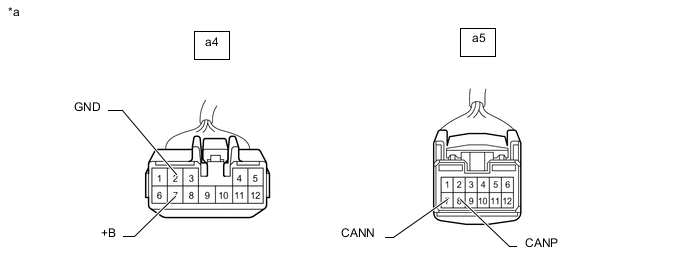
*a Front view of wire harness connector
(to Position Control ECU and Switch Assembly RH)
- - Measure the resistance according to the value(s) in the table below.
Standard Resistance Terminal No. (Symbol) Wiring Color Terminal Description Condition Specified Condition a5-8 (CANP) - a5-7 (CANN) L - W HIGH-level CAN bus line - LOW-level CAN bus line Cable disconnected from negative (-) battery terminal 54 to 69 Ω a5-8 (CANP) - a4-2 (GND) L - W-B HIGH-level CAN bus line - Ground Cable disconnected from negative (-) battery terminal 200 Ω or higher a5-7 (CANN) - a4-2 (GND) W - W-B LOW-level CAN bus line - Ground Cable disconnected from negative (-) battery terminal 200 Ω or higher a5-8 (CANP) - a4-7 (+B) L - W HIGH-level CAN bus line - Battery positive (+) Cable disconnected from negative (-) battery terminal 6 kΩ or higher a5-7 (CANN) - a4-7 (+B) W - W LOW-level CAN bus line - Battery positive (+) Cable disconnected from negative (-) battery terminal 6 kΩ or higher
-
-
MULTIPLEX TILT AND TELESCOPIC ECU
Refer to Terminals of ECU.
-
Disconnect the cable from the negative (-) battery terminal.
-
Disconnect the O18 multiplex tilt and telescopic ECU connector.
-
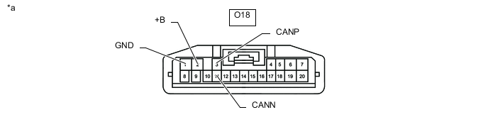
*a Front view of wire harness connector
(to Multiplex Tilt and Telescopic ECU)
- - Measure the resistance according to the value(s) in the table below.
Standard Resistance Terminal No. (Symbol) Wiring Color Terminal Description Condition Specified Condition O18-3 (CANP) - O18-11 (CANN) G - B HIGH-level CAN bus line - LOW-level CAN bus line Cable disconnected from negative (-) battery terminal 54 to 69 Ω O18-3 (CANP) - O18-1 (GND) G - W-B HIGH-level CAN bus line - Ground Cable disconnected from negative (-) battery terminal 200 Ω or higher O18-11 (CANN) - O18-1 (GND) B - W-B LOW-level CAN bus line - Ground Cable disconnected from negative (-) battery terminal 200 Ω or higher O18-3 (CANP) - O18-2 (+B) G - SB HIGH-level CAN bus line - Battery positive (+) Cable disconnected from negative (-) battery terminal 6 kΩ or higher O18-11 (CANN) - O18-2 (+B) B - SB LOW-level CAN bus line - Battery positive (+) Cable disconnected from negative (-) battery terminal 6 kΩ or higher
-
-
BLIND SPOT MONITOR SENSOR LH (w/ Blind Spot Monitor System)
Refer to Terminals of ECU.
-
Disconnect the cable from the negative (-) battery terminal.
-
Disconnect the U48 blind spot monitor sensor LH connector.
-
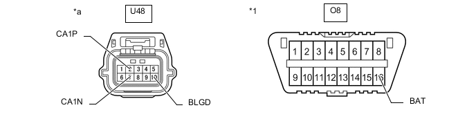
*1 DLC3 - - *a Front view of wire harness connector
(to Blind Spot Monitor Sensor LH)
- - Measure the resistance according to the value(s) in the table below.
Standard Resistance Terminal No. (Symbol) Wiring Color Terminal Description Condition Specified Condition U48-2 (CA1P) - U48-7 (CA1N) R - B HIGH-level CAN bus line - LOW-level CAN bus line Cable disconnected from negative (-) battery terminal 54 to 69 Ω U48-2 (CA1P) - U48-10 (BLGD) R - BR HIGH-level CAN bus line - Ground Cable disconnected from negative (-) battery terminal 200 Ω or higher U48-7 (CA1N) - U48-10 (BLGD) B - BR LOW-level CAN bus line - Ground Cable disconnected from negative (-) battery terminal 200 Ω or higher U48-2 (CA1P) - O8-16 (BAT) R - L HIGH-level CAN bus line - Battery positive (+) Cable disconnected from negative (-) battery terminal 6 kΩ or higher U48-7 (CA1N) - O8-16 (BAT) B - L LOW-level CAN bus line - Battery positive (+) Cable disconnected from negative (-) battery terminal 6 kΩ or higher
-
-
DRIVING SUPPORT ECU ASSEMBLY (w/ Lexus Safety System +)
Refer to Terminals of ECU.
-
Disconnect the cable from the negative (-) battery terminal.
-
Disconnect the Q2 driving support ECU assembly connector.
-
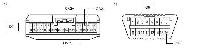
*1 DLC3 - - *a Front view of wire harness connector
(to Driving Support ECU Assembly)
- - Measure the resistance according to the value(s) in the table below.
Standard Resistance Terminal No. (Symbol) Wiring Color Terminal Description Condition Specified Condition Q2-10 (CA2H) - Q2-11 (CA2L) G - B HIGH-level CAN bus line - LOW-level CAN bus line Cable disconnected from negative (-) battery terminal 54 to 69 Ω Q2-10 (CA2H) - Q2-28 (GND) G - BR HIGH-level CAN bus line - Ground Cable disconnected from negative (-) battery terminal 200 Ω or higher Q2-11 (CA2L) - Q2-28 (GND) B - BR LOW-level CAN bus line - Ground Cable disconnected from negative (-) battery terminal 200 Ω or higher Q2-10 (CA2H) - O8-16 (BAT) G - L HIGH-level CAN bus line - Battery positive (+) Cable disconnected from negative (-) battery terminal 6 kΩ or higher Q2-11 (CA2L) - O8-16 (BAT) B - L LOW-level CAN bus line - Battery positive (+) Cable disconnected from negative (-) battery terminal 6 kΩ or higher
-
-
MILLIMETER WAVE RADAR SENSOR ASSEMBLY (w/ Lexus Safety System +)
Refer to Terminals of ECU.
-
Disconnect the cable from the negative (-) battery terminal.
-
Disconnect the B9 millimeter wave radar sensor assembly connector.
-
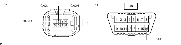
*1 DLC3 - - *a Front view of wire harness connector
(to Millimeter Wave Radar Sensor Assembly)
- - Measure the resistance according to the value(s) in the table below.
Standard Resistance Terminal No. (Symbol) Wiring Color Terminal Description Condition Specified Condition B9-3 (CA2H) - B9-2 (CA2L) L - B HIGH-level CAN bus line - LOW-level CAN bus line Cable disconnected from negative (-) battery terminal 54 to 69 Ω B9-3 (CA2H) - B9-1 (SGND) L - BR HIGH-level CAN bus line - Ground Cable disconnected from negative (-) battery terminal 200 Ω or higher B9-2 (CA2L) - B9-1 (SGND) B - BR LOW-level CAN bus line - Ground Cable disconnected from negative (-) battery terminal 200 Ω or higher B9-3 (CA2H) - O8-16 (BAT) L - L HIGH-level CAN bus line - Battery positive (+) Cable disconnected from negative (-) battery terminal 6 kΩ or higher B9-2 (CA2L) - O8-16 (BAT) B - L LOW-level CAN bus line - Battery positive (+) Cable disconnected from negative (-) battery terminal 6 kΩ or higher
-
-
OPTION CONNECTOR (BUS BUFFER ECU) (w/ Option Connector)
-
Disconnect the cable from the negative (-) battery terminal.
-
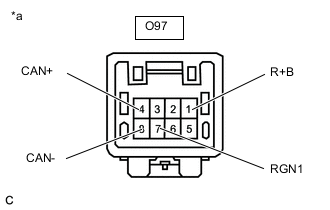
*a Front view of wire harness connector
(to Option Connector (Bus Buffer ECU))
Measure the resistance according to the value(s) in the table below.
Standard Resistance Terminal No. (Symbol) Wiring Color Terminal Description Condition Specified Condition O97-4 (CAN+) - O97-8 (CAN-) SB - B HIGH-level CAN bus line - LOW-level CAN bus line Cable disconnected from negative (-) battery terminal 54 to 69 Ω O97-4 (CAN+) - O97-7 (RGN1) SB - W-B HIGH-level CAN bus line - Ground Cable disconnected from negative (-) battery terminal 200 Ω or higher O97-8 (CAN-) - O97-7 (RGN1) B - W-B LOW-level CAN bus line - Ground Cable disconnected from negative (-) battery terminal 200 Ω or higher O97-4 (CAN+) - O97-1 (R+B) SB - LG HIGH-level CAN bus line - Battery positive (+) Cable disconnected from negative (-) battery terminal 6 kΩ or higher O97-8 (CAN-) - O97-1 (R+B) B - LG LOW-level CAN bus line - Battery positive (+) Cable disconnected from negative (-) battery terminal 6 kΩ or higher
-
-
CLEARANCE WARNING ECU ASSEMBLY
Refer to Terminals of ECU.
-
Disconnect the cable from the negative (-) battery terminal.
-
Disconnect the O43 clearance warning ECU assembly connector.
-
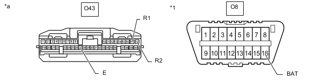
*1 DLC3 - - *a Front view of wire harness connector
(to Clearance Warning ECU Assembly)
- - Measure the resistance according to the value(s) in the table below.
Standard Resistance Terminal No. (Symbol) Wiring Color Terminal Description Condition Specified Condition O43-17 (R1) - O43-18 (R2) SB - B HIGH-level CAN bus line - LOW-level CAN bus line Cable disconnected from negative (-) battery terminal 54 to 69 Ω O43-17 (R1) - O43-27 (E) SB - BR HIGH-level CAN bus line - Ground Cable disconnected from negative (-) battery terminal 200 Ω or higher O43-18 (R2) - O43-27 (E) B - BR LOW-level CAN bus line - Ground Cable disconnected from negative (-) battery terminal 200 Ω or higher O43-17 (R1) - O8-16 (BAT) SB - L HIGH-level CAN bus line - Battery positive (+) Cable disconnected from negative (-) battery terminal 6 kΩ or higher O43-18 (R2) - O8-16 (BAT) B - L LOW-level CAN bus line - Battery positive (+) Cable disconnected from negative (-) battery terminal 6 kΩ or higher
-
-
FORWARD RECOGNITION CAMERA (w/ Lexus Safety System +)
Refer to Terminals of ECU.
-
Disconnect the cable from the negative (-) battery terminal.
-
Disconnect the W18 forward recognition camera connector.
-
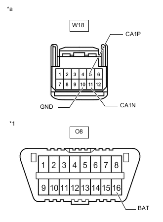
*1 DLC3 *a Front view of wire harness connector
(to Forward Recognition Camera)
Measure the resistance according to the value(s) in the table below.
Standard Resistance Terminal No. (Symbol) Wiring Color Terminal Description Condition Specified Condition W18-5 (CA1P) - W18-11 (CA1N) R - B HIGH-level CAN bus line - LOW-level CAN bus line Cable disconnected from negative (-) battery terminal 54 to 69 Ω W18-5 (CA1P) - W18-10 (GND) R - BR HIGH-level CAN bus line - Ground Cable disconnected from negative (-) battery terminal 200 Ω or higher W18-11 (CA1N) - W18-10 (GND) B - BR LOW-level CAN bus line - Ground Cable disconnected from negative (-) battery terminal 200 Ω or higher W18-5 (CA1P) - O8-16 (BAT) R - L HIGH-level CAN bus line - Battery positive (+) Cable disconnected from negative (-) battery terminal 6 kΩ or higher W18-11 (CA1N) - O8-16 (BAT) B - L LOW-level CAN bus line - Battery positive (+) Cable disconnected from negative (-) battery terminal 6 kΩ or higher
-
-

*a Component without harness connected
(Roll Rate and Vertical Acceleration Sensor)
- - ROLL RATE AND VERTICAL ACCELERATION SENSOR
-
Disconnect the cable from the negative (-) battery terminal.
-
Disconnect the E1 roll rate and vertical acceleration sensor connector.
-
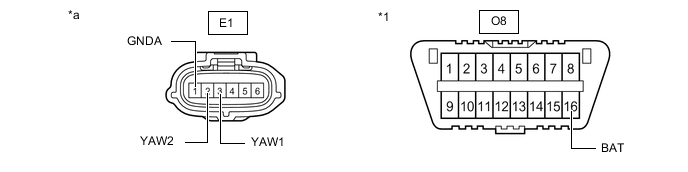
*1 DLC3 - - *a Front view of wire harness connector
(to Roll Rate and Vertical Acceleration Sensor)
- - Measure the resistance according to the value(s) in the table below.
Standard Resistance Terminal No. (Symbol) Wiring Color Terminal Description Condition Specified Condition E1-3 (YAW1) - E1-2 (YAW2) G - B HIGH-level CAN bus line - LOW-level CAN bus line Cable disconnected from negative (-) battery terminal 54 to 69 Ω E1-3 (YAW1) - E1-1 (GNDA) G - BR HIGH-level CAN bus line - Ground Cable disconnected from negative (-) battery terminal 200 Ω or higher E1-2 (YAW2) - E1-1 (GNDA) B - BR LOW-level CAN bus line - Ground Cable disconnected from negative (-) battery terminal 200 Ω or higher E1-3 (YAW1) - O8-16 (BAT) G - L HIGH-level CAN bus line - Battery positive (+) Cable disconnected from negative (-) battery terminal 6 kΩ or higher E1-2 (YAW2) - O8-16 (BAT) B - L LOW-level CAN bus line - Battery positive (+) Cable disconnected from negative (-) battery terminal 6 kΩ or higher
-
-
STEREO COMPONENT EQUALIZER ASSEMBLY
Refer to Terminals of ECU.
-
Disconnect the cable from the negative (-) battery terminal.
-
Disconnect the O31 stereo component equalizer assembly connector.
-
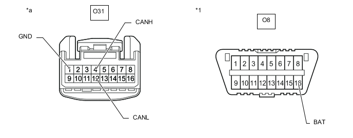
*1 DLC3 - - *a Front view of wire harness connector
(to Stereo Component Equalizer Assembly)
- - Measure the resistance according to the value(s) in the table below.
Standard Resistance Terminal No. (Symbol) Wiring Color Terminal Description Condition Specified Condition O31-4 (CANH) - O31-12 (CANL) G - B HIGH-level CAN bus line - LOW-level CAN bus line Cable disconnected from negative (-) battery terminal 54 to 69 Ω O31-4 (CANH) - O31-1 (GND) G - W-B HIGH-level CAN bus line - Ground Cable disconnected from negative (-) battery terminal 200 Ω or higher O31-12 (CANL) - O31-1 (GND) B - W-B LOW-level CAN bus line - Ground Cable disconnected from negative (-) battery terminal 200 Ω or higher O31-4 (CANH) - O8-16 (BAT) G - L HIGH-level CAN bus line - Battery positive (+) Cable disconnected from negative (-) battery terminal 6 kΩ or higher O31-12 (CANL) - O8-16 (BAT) B - L LOW-level CAN bus line - Battery positive (+) Cable disconnected from negative (-) battery terminal 6 kΩ or higher
-
-
SPOILER CONTROL ECU ASSEMBLY
Refer to Terminals of ECU.
-
Disconnect the cable from the negative (-) battery terminal.
-
Disconnect the U38 spoiler control ECU assembly connector.
-
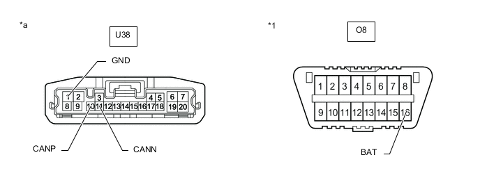
*1 DLC3 - - *a Front view of wire harness connector
(to Spoiler Control ECU Assembly)
- - Measure the resistance according to the value(s) in the table below.
Standard Resistance Terminal No. (Symbol) Wiring Color Terminal Description Condition Specified Condition U38-10 (CANP) - U38-11 (CANN) GR - B HIGH-level CAN bus line - LOW-level CAN bus line Cable disconnected from negative (-) battery terminal 54 to 69 Ω U38-10 (CANP) - U38-1 (GND) GR - W-B HIGH-level CAN bus line - Ground Cable disconnected from negative (-) battery terminal 200 Ω or higher U38-11 (CANN) - U38-1 (GND) B - W-B LOW-level CAN bus line - Ground Cable disconnected from negative (-) battery terminal 200 Ω or higher U38-10 (CANP) - O8-16 (BAT) GR - L HIGH-level CAN bus line - Battery positive (+) Cable disconnected from negative (-) battery terminal 6 kΩ or higher U38-11 (CANN) - O8-16 (BAT) B - L LOW-level CAN bus line - Battery positive (+) Cable disconnected from negative (-) battery terminal 6 kΩ or higher
-
-
TORQUE VECTORING DIFFERENTIAL ECU ASSEMBLY (w/ Torque Vectoring Differential System)
Refer to Terminals of ECU.
-
Disconnect the cable from the negative (-) battery terminal.
-
Disconnect the T27 and T43 torque vectoring differential ECU assembly connectors.
-
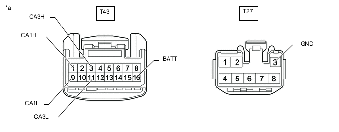
*a Front view of wire harness connector
(to Torque Vectoring Differential ECU Assembly)
- - Measure the resistance according to the value(s) in the table below.
Standard Resistance Table 10. Bus 2 Branch Lines Terminal No. (Symbol) Wiring Color Terminal Description Condition Specified Condition T43-1 (CA1H) - T43-9 (CA1L) P - B HIGH-level CAN bus line - LOW-level CAN bus line Cable disconnected from negative (-) battery terminal 54 to 69 Ω T43-1 (CA1H) - T27-3 (GND) P - W-B HIGH-level CAN bus line - Ground Cable disconnected from negative (-) battery terminal 200 Ω or higher T43-9 (CA1L) - T27-3 (GND) B - W-B LOW-level CAN bus line - Ground Cable disconnected from negative (-) battery terminal 200 Ω or higher T43-1 (CA1H) - T43-16 (BATT) P - LG HIGH-level CAN bus line - Battery positive (+) Cable disconnected from negative (-) battery terminal 6 kΩ or higher T43-9 (CA1L) - T43-16 (BATT) B - LG LOW-level CAN bus line - Battery positive (+) Cable disconnected from negative (-) battery terminal 6 kΩ or higher Table 11. V3 Bus Branch Lines Terminal No. (Symbol) Wiring Color Terminal Description Condition Specified Condition T43-3 (CA3H) - T43-11 (CA3L) V - B HIGH-level CAN bus line - LOW-level CAN bus line Cable disconnected from negative (-) battery terminal 54 to 69 Ω T43-3 (CA3H) - T27-3 (GND) V - W-B HIGH-level CAN bus line - Ground Cable disconnected from negative (-) battery terminal 200 Ω or higher T43-11 (CA3L) - T27-3 (GND) B - W-B LOW-level CAN bus line - Ground Cable disconnected from negative (-) battery terminal 200 Ω or higher T43-3 (CA3H) - T43-16 (BATT) V - LG HIGH-level CAN bus line - Battery positive (+) Cable disconnected from negative (-) battery terminal 6 kΩ or higher T43-11 (CA3L) - T43-16 (BATT) B - LG LOW-level CAN bus line - Battery positive (+) Cable disconnected from negative (-) battery terminal 6 kΩ or higher
-
-
REAR TELEVISION CAMERA ASSEMBLY
Refer to Terminals of ECU.
-
Disconnect the cable from the negative (-) battery terminal.
-
Disconnect the z22 rear television camera assembly connector.
-
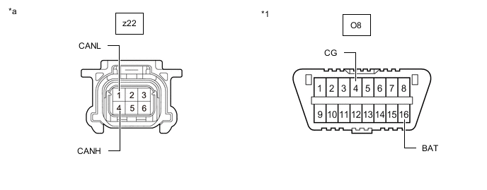
*1 DLC3 - - *a Front view of wire harness connector
(to Rear Television Camera Assembly)
- - Measure the resistance according to the value(s) in the table below.
Standard Resistance Terminal No. (Symbol) Wiring Color Terminal Description Condition Specified Condition z22-4 (CANH) - z22-1 (CANL) L - G HIGH-level CAN bus line - LOW-level CAN bus line Cable disconnected from negative (-) battery terminal 54 to 69 Ω z22-4 (CANH) - O8-4 (CG) L - W-B HIGH-level CAN bus line - Ground Cable disconnected from negative (-) battery terminal 200 Ω or higher z22-1 (CANL) - O8-4 (CG) G - W-B LOW-level CAN bus line - Ground Cable disconnected from negative (-) battery terminal 200 Ω or higher z22-4 (CANH) - O8-16 (BAT) L - L HIGH-level CAN bus line - Battery positive (+) Cable disconnected from negative (-) battery terminal 6 kΩ or higher z22-1 (CANL) - O8-16 (BAT) G - L LOW-level CAN bus line - Battery positive (+) Cable disconnected from negative (-) battery terminal 6 kΩ or higher
-
-
ABSORBER CONTROL ECU
Refer to Terminals of ECU.
-
Disconnect the cable from the negative (-) battery terminal.
-
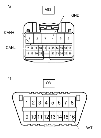
*1 DLC3 *a Front view of wire harness connector
(to Absorber Control ECU)
Disconnect the A83 absorber control ECU connector.
-
Measure the resistance according to the value(s) in the table below.
Standard Resistance Terminal No. (Symbol) Wiring Color Terminal Description Condition Specified Condition A83-8 (CANH) - A83-7 (CANL) SB - B HIGH-level CAN bus line - LOW-level CAN bus line Cable disconnected from negative (-) battery terminal 54 to 69 Ω A83-8 (CANH) - A83-4 (GND) SB - W-B HIGH-level CAN bus line - Ground Cable disconnected from negative (-) battery terminal 200 Ω or higher A83-7 (CANL) - A83-4 (GND) B - W-B LOW-level CAN bus line - Ground Cable disconnected from negative (-) battery terminal 200 Ω or higher A83-8 (CANH) - O8-16 (BAT) SB - L HIGH-level CAN bus line - Battery positive (+) Cable disconnected from negative (-) battery terminal 6 kΩ or higher A83-7 (CANL) - O8-16 (BAT) B - L LOW-level CAN bus line - Battery positive (+) Cable disconnected from negative (-) battery terminal 6 kΩ or higher
-