CAN COMMUNICATION SYSTEM TERMINALS OF ECU
Note
-
After turning the engine switch off, waiting time may be required before disconnecting the cable from the negative (-) battery terminal. Therefore, make sure to read the disconnecting the cable from the negative (-) battery terminal notices before proceeding with work.
-
Turn the engine switch off before measuring the resistances between CAN main bus lines and between CAN branch lines.
-
Turn the engine switch off before inspecting CAN bus lines for a short to ground.
-
Before measuring the resistance of the CAN bus, turn the engine switch off and leave the vehicle for 1 minute or more without operating the key or any switches, or opening or closing the doors. After that, disconnect the cable from the negative (-) battery terminal and leave the vehicle for 1 minute or more before measuring the resistance.
-
This section describes the standard values for all CAN related components.
Tech Tips
-
Operating the engine switch, any other switches or a door triggers related ECU and sensor communication on the CAN. This communication will cause the resistance value to change.
-
Even after DTCs are cleared, if a DTC is stored again after driving the vehicle for a while, the malfunction may be occurring due to vibration of the vehicle. In such a case, wiggling the ECUs or wire harness while performing the inspection below may help determine the cause of the malfunction.
-
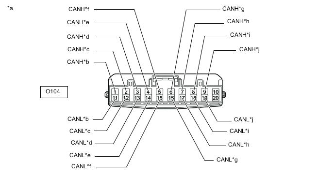
NO. 1 CAN JUNCTION CONNECTOR (for LHD)
-
Check the No. 1 CAN junction connector.
-
Connection diagram

*a Front view of wire harness connector
(to No. 1 CAN Junction Connector)
*b to No. 2 CAN Junction Connector
(for V Bus)
*c to Combination Meter Assembly
(for V Bus)
*d to Radio Receiver Assembly
(for V Bus)
*e to Network Gateway ECU
(for V Bus)
*f to Air Conditioning Amplifier Assembly
(for V Bus)
*g to Stereo Component Equalizer Assembly
(for V Bus)
*h to Certification ECU (Smart Key ECU Assembly)
(for V Bus)
*i to Torque Vectoring Differential ECU Assembly
(w/ Torque Vectoring Differential System)
(for V Bus)
*j to Power Steering ECU Assembly
(for V Bus)
-
Check the connection diagram of the components which are connected to the No. 1 CAN junction connector.
Terminal No. (Symbol) Wiring Color Connected to O104-1 (CANH) L No. 2 CAN junction connector
(for V bus)
O104-11 (CANL) B O104-2 (CANH) LG Combination meter assembly
(for V bus)
O104-12 (CANL) B O104-3 (CANH) R Radio receiver assembly
(for V bus)
O104-13 (CANL) B O104-4 (CANH) BE Network gateway ECU
(for V bus)
O104-14 (CANL) B O104-5 (CANH) P Air conditioning amplifier assembly
(for V bus)
O104-15 (CANL) B O104-6 (CANH) G Stereo component equalizer assembly
(for V bus)
O104-16 (CANL) B O104-7 (CANH) W Certification ECU (smart key ECU assembly)
(for V bus)
O104-17 (CANL) B O104-8 (CANH) P Torque vectoring differential ECU assembly*
(for V bus)
O104-18 (CANL) B O104-9 (CANH) G Power steering ECU assembly
(for V bus)
O104-19 (CANL) B
-
*: w/ Torque Vectoring Differential System
-
-
-
-
NO. 2 CAN JUNCTION CONNECTOR (for LHD)
-
Check the No. 2 CAN junction connector.
-
Connection diagram
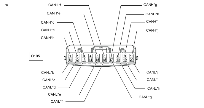
*a Front view of wire harness connector
(to No. 2 CAN Junction Connector)
*b to No. 1 CAN Junction Connector
(for V Bus)
*c to Main Body ECU (Multiplex Network Body ECU)
(for V Bus)
*d to ECM
(for V Bus)
*e to Airbag ECU Assembly
(for V Bus)
*f to Yaw Rate Sensor
(for V Bus)
*g to Spoiler Control ECU Assembly
(for V Bus)
*h to DLC3
(for V Bus)
*i to Steering Sensor
(for V Bus)
*j to Skid Control ECU (Brake Actuator Assembly)
(for V Bus)
-
Check the connection diagram of the components which are connected to the No. 2 CAN junction connector.
Terminal No. (Symbol) Wiring Color Connected to O105-1 (CANH) L No. 1 CAN junction connector
(for V bus)
O105-11 (CANL) B O105-2 (CANH) Y Main body ECU (multiplex network body ECU)
(for V bus)
O105-12 (CANL) B O105-3 (CANH) R ECM
(for V bus)
O105-13 (CANL) B O105-5 (CANH) BE Airbag ECU assembly
(for V bus)
O105-15 (CANL) B O105-6 (CANH) G Yaw rate sensor
(for V bus)
O105-16 (CANL) B O105-7 (CANH) GR Spoiler control ECU assembly
(for V bus)
O105-17 (CANL) B O105-8 (CANH) W DLC3
(for V bus)
O105-18 (CANL) B O105-9 (CANH) P Steering sensor
(for V bus)
O105-19 (CANL) B O105-10 (CANH) SB Skid control ECU (brake actuator assembly)
(for V bus)
O105-20 (CANL) B
-
-
-
NO. 3 CAN JUNCTION CONNECTOR (for LHD)
-
Check the No. 3 CAN junction connector.
-
Connection diagram
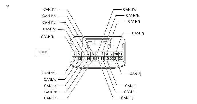
*a Front view of wire harness connector
(to No. 3 CAN Junction Connector)
*b to Multiplex Tilt and Telescopic ECU
(for Sub Bus 1)
*c to No. 9 CAN Junction Connector
(for Sub Bus 1)
*d to Main Body ECU (Multiplex Network Body ECU)
(for Sub Bus 1)
*e to Outer Mirror Control ECU Assembly (for Driver Side)
(for Sub Bus 1)
*f to Headlight Light Control ECU Sub-assembly LH
(for Sub Bus 1)
*g to Position Control ECU and Switch Assembly LH
(for Sub Bus 1)
*h to No. 5 CAN Junction Connector
(for Sub Bus 2)
*i to No. 10 CAN Junction Connector
(for Sub Bus 2)
*j to Driving Support ECU Assembly
(w/ Pre-crash Safety System)
(for Sub Bus 2)
-
Check the connection diagram of the components which are connected to the No. 3 CAN junction connector.
Terminal No. (Symbol) Wiring Color Connected to O106-1 (CANH) G Multiplex tilt and telescopic ECU
(for Sub bus 1)
O106-12 (CANL) B O106-2 (CANH) L No. 9 CAN junction connector
(for Sub bus 1)
O106-13 (CANL) B O106-3 (CANH) P Main body ECU (multiplex network body ECU)
(for Sub bus 1)
O106-14 (CANL) B O106-4 (CANH) W Outer mirror control ECU assembly (for driver side)
(for Sub bus 1)
O106-15 (CANL) B O106-5 (CANH) V Headlight light control ECU sub-assembly LH
(for Sub bus 1)
O106-16 (CANL) B O106-6 (CANH) R Position control ECU and switch assembly LH
(for Sub bus 1)
O106-17 (CANL) B O106-7 (CANH) L No. 5 CAN junction connector
(for Sub bus 2)
O106-18 (CANL) B O106-8 (CANH) LG No. 10 CAN junction connector
(for Sub bus 2)
O106-19 (CANL) B O106-10 (CANH) G Driving support ECU assembly*
(for Sub bus 2)
O106-21 (CANL) B
-
*: w/ Pre-crash Safety System
-
-
-
-
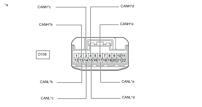
NO. 5 CAN JUNCTION CONNECTOR (for LHD)
-
Check the No. 5 CAN junction connector.
-
Connection diagram
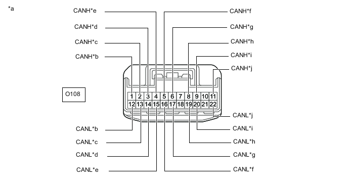
*a Front view of wire harness connector
(to No. 5 CAN Junction Connector)
*b to Clearance Warning ECU Assembly
(for Sub bus 2)
*c to Network Gateway ECU
(for Sub bus 2)
*d to No. 3 CAN Junction Connector
(for Sub bus 2)
*e to Option Connector (Bus Buffer ECU)
(w/ Option Connector)
(for Sub bus 2)
*f to Telematics Transceiver
(w/ Telematics Transceiver)
(for Sub bus 2)
*g to Absorber Control ECU
(for Sub bus 2)
*h to No. 8 CAN Junction Connector
(for V3 Bus)
*i to Roll Rate and Vertical Acceleration Sensor
(for V3 Bus)
*j to ECM
(for V3 Bus)
-
Check the connection diagram of the components which are connected to the No. 5 CAN junction connector.
Terminal No. (Symbol) Wiring Color Connected to O108-1 (CANH) SB Clearance warning ECU assembly
(for Sub bus 2)
O108-12 (CANL) B O108-2 (CANH) R Network gateway ECU
(for Sub bus 2)
O108-13 (CANL) B O108-3 (CANH) L No. 3 CAN junction connector
(for Sub bus 2)
O108-14 (CANL) B O108-4 (CANH) R Option connector (bus buffer ECU)*1
(for Sub bus 2)
O108-15 (CANL) B O108-5 (CANH) SB Telematics transceiver*2
(for Sub bus 2)
O108-16 (CANL) B O108-6 (CANH) SB Absorber control ECU
(for Sub bus 2)
O108-17 (CANL) B O108-8 (CANH) R No. 8 CAN junction connector
(for V3 bus)
O108-19 (CANL) B O108-9 (CANH) G Roll rate and vertical acceleration sensor
(for V3 bus)
O108-20 (CANL) B O108-11 (CANH) L ECM
(for V3 bus)
O108-22 (CANL) B
-
*1: w/ Option Connector
-
*2: w/ Telematics Transceiver
-
-
-
-
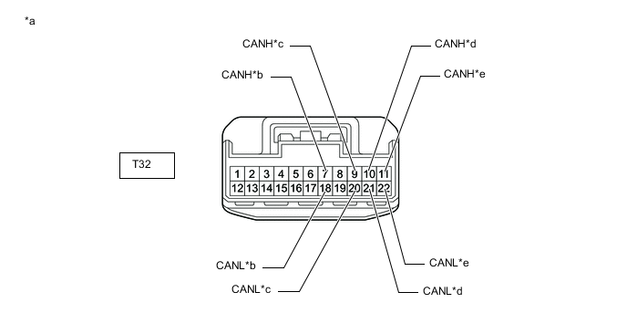
NO. 7 CAN JUNCTION CONNECTOR (for LHD)
-
Check the No. 7 CAN junction connector.
-
Connection diagram

*a Front view of wire harness connector
(to No. 7 CAN Junction Connector)
*b to No. 9 CAN Junction Connector
(for Sub Bus 1)
*c to Position Control ECU and Switch Assembly RH
(for Sub Bus 1)
*d to Outer Mirror Control ECU Assembly (for Front Passenger Side)
(for Sub Bus 1)
*e to No. 1 CAN Junction Terminal
(for Sub Bus 1)
- - -
Check the connection diagram of the components which are connected to the No. 7 CAN junction connector.
Terminal No. (Symbol) Wiring Color Connected to T32-7 (CANH) LG No. 9 CAN junction connector
(for Sub bus 1)
T32-18 (CANL) B T32-9 (CANH) R Position control ECU and switch assembly RH
(for Sub bus 1)
T32-20 (CANL) B T32-10 (CANH) W Outer mirror control ECU assembly (for front passenger side)
(for Sub bus 1)
T32-21 (CANL) B T32-11 (CANH) P No. 1 CAN junction terminal
(for Sub bus 1)
T32-22 (CANL) B
-
-
-
NO. 8 CAN JUNCTION CONNECTOR (for LHD)
-
Check the No. 8 CAN junction connector.
-
Connection diagram
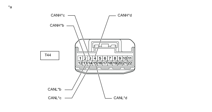
*a Front view of wire harness connector
(to No. 8 CAN Junction Connector)
*b to Torque Vectoring Differential ECU Assembly
(w/ Torque Vectoring Differential System)
(for V3 Bus)
*c to Skid Control ECU (Brake Actuator Assembly)
(for V3 Bus)
*d to No. 5 CAN Junction Connector
(for V3 Bus)
-
Check the connection diagram of the components which are connected to the No. 8 CAN junction connector.
Terminal No. (Symbol) Wiring Color Connected to T44-2 (CANH) V Torque vectoring differential ECU assembly*
(for V3 bus)
T44-13 (CANL) B T44-3 (CANH) LG Skid control ECU (brake actuator assembly)
(for V3 bus)
T44-14 (CANL) B T44-4 (CANH) R No. 5 CAN junction connector
(for V3 bus)
T44-15 (CANL) B
-
*: w/ Torque Vectoring Differential System
-
-
-
-
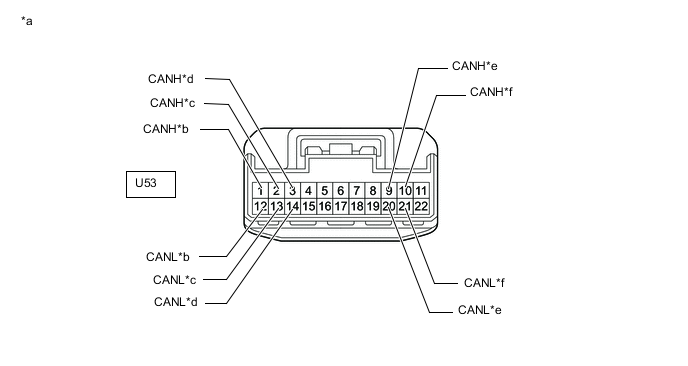
NO. 9 CAN JUNCTION CONNECTOR (for LHD)
-
Check the No. 9 CAN junction connector.
-
Connection diagram
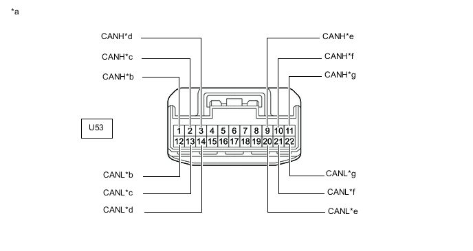
*a Front view of wire harness connector
(to No. 9 CAN Junction Connector)
*b to No. 10 CAN Junction Connector
(for Sub Bus 2)
*c to No. 2 CAN Junction Terminal
(for Sub Bus 2)
*d to Blind Spot Monitor Sensor LH
(w/ Blind Spot Monitor System)
(for Sub Bus 2)
*e to No. 7 CAN Junction Connector
(for Sub Bus 1)
*f to No. 3 CAN Junction Connector
(for Sub Bus 1)
*g to Rear Television Camera Assembly
(w/ Parking Assist Monitor System w/o Parallel Parking Assist Function)
(for Sub Bus 1)
- - -
Check the connection diagram of the components which are connected to the No. 9 CAN junction connector.
Terminal No. (Symbol) Wiring Color Connected to U53-1 (CANH) BE No. 10 CAN junction connector
(for Sub bus 2)
U53-12 (CANL) B U53-2 (CANH) V No. 2 CAN junction terminal
(for Sub bus 2)
U53-13 (CANL) B U53-3 (CANH) R Blind spot monitor sensor LH*1
(for Sub bus 2)
U53-14 (CANL) B U53-9 (CANH) LG No. 7 CAN junction connector
(for Sub bus 1)
U53-20 (CANL) B U53-10 (CANH) L No. 3 CAN junction connector
(for Sub bus 1)
U53-21 (CANL) B U53-11 (CANH) L Rear television camera assembly*2
(for Sub bus 1)
U53-22 (CANL) B
-
*1: w/ Blind Spot Monitor System
-
*2: w/ Parking Assist Monitor System w/o Parallel Parking Assist Function
-
-
-
-
NO. 10 CAN JUNCTION CONNECTOR (for LHD)
-
Check the No. 10 CAN junction connector.
-
Connection diagram
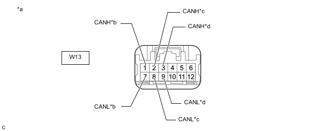
*a Front view of wire harness connector
(to No. 10 CAN Junction Connector)
*b to No. 3 CAN Junction Connector
(for Sub Bus 2)
*c to No. 9 CAN Junction Connector
(for Sub Bus 2)
*d to Lane Departure Warning Camera
(w/ Lane Departure Alert System)
(for Sub Bus 2)
-
Check the connection diagram of the components which are connected to the No. 10 CAN junction connector.
Terminal No. (Symbol) Wiring Color Connected to W13-1 (CANH) LG No. 3 CAN junction connector
(for Sub bus 2)
W13-7 (CANL) B W13-2 (CANH) BE No. 9 CAN junction connector
(for Sub bus 2)
W13-8 (CANL) B W13-3 (CANH) R Lane departure warning camera*
(for Sub bus 2)
W13-9 (CANL) B
-
*: w/ Lane Departure Alert System
-
-
-
-
NO. 1 CAN JUNCTION CONNECTOR (for RHD)
-
Check the No. 1 CAN junction connector.
-
Connection diagram
*a Front view of wire harness connector
(to No. 1 CAN Junction Connector)
*b to No. 2 CAN Junction Connector
(for V Bus)
*c to Combination Meter Assembly
(for V Bus)
*d to Radio Receiver Assembly
(for V Bus)
*e to Airbag ECU Assembly
(for V Bus)
*f to Stereo Component Equalizer Assembly
(for V Bus)
*g to Skid Control ECU (Brake Actuator Assembly)
(for V Bus)
*h to Steering Sensor
(for V Bus)
*i to DLC3
(for V Bus)
*j to Torque Vectoring Differential ECU Assembly
(w/ Torque Vectoring Differential System)
(for V Bus)
-
Check the connection diagram of the components which are connected to the No. 1 CAN junction connector.
Terminal No. (Symbol) Wiring Color Connected to O104-1 (CANH) L No. 2 CAN junction connector
(for V bus)
O104-11 (CANL) B O104-2 (CANH) LG Combination meter assembly
(for V bus)
O104-12 (CANL) B O104-3 (CANH) R Radio receiver assembly
(for V bus)
O104-13 (CANL) B O104-4 (CANH) BE Airbag ECU assembly
(for V bus)
O104-14 (CANL) B O104-5 (CANH) G Stereo component equalizer assembly
(for V bus)
O104-15 (CANL) B O104-6 (CANH) SB Skid control ECU (brake actuator assembly)
(for V bus)
O104-16 (CANL) B O104-7 (CANH) P Steering sensor
(for V bus)
O104-17 (CANL) B O104-8 (CANH) W DLC3
(for V bus)
O104-18 (CANL) B O104-9 (CANH) P Torque vectoring differential ECU assembly*
(for V bus)
O104-19 (CANL) B
-
*: w/ Torque Vectoring Differential System
-
-
-
-
NO. 2 CAN JUNCTION CONNECTOR (for RHD)
-
Check the No. 2 CAN junction connector.
-
Connection diagram

*a Front view of wire harness connector
(to No. 2 CAN Junction Connector)
*b to No. 1 CAN Junction Connector
(for V Bus)
*c to Main Body ECU (Multiplex Network Body ECU)
(for V Bus)
*d to ECM
(for V Bus)
*e to Network Gateway ECU
(for V Bus)
*f to Air Conditioning Amplifier Assembly
(for V Bus)
*g to Yaw Rate Sensor
(for V Bus)
*h to Certification ECU (Smart Key ECU Assembly)
(for V Bus)
*i to Spoiler Control ECU Assembly
(for V Bus)
*j to Power Steering ECU Assembly
(for V Bus)
-
Check the connection diagram of the components which are connected to the No. 2 CAN junction connector.
Terminal No. (Symbol) Wiring Color Connected to O105-1 (CANH) L No. 1 CAN junction connector
(for V bus)
O105-11 (CANL) B O105-2 (CANH) Y Main body ECU (multiplex network body ECU)
(for V bus)
O105-12 (CANL) B O105-3 (CANH) R ECM
(for V bus)
O105-13 (CANL) B O105-5 (CANH) BE Network gateway ECU
(for V bus)
O105-15 (CANL) B O105-6 (CANH) P Air conditioning amplifier assembly
(for V bus)
O105-16 (CANL) B O105-7 (CANH) G Yaw rate sensor
(for V bus)
O105-17 (CANL) B O105-8 (CANH) W Certification ECU (smart key ECU assembly)
(for V bus)
O105-18 (CANL) B O105-9 (CANH) GR Spoiler control ECU assembly
(for V bus)
O105-19 (CANL) B O105-10 (CANH) G Power steering ECU assembly
(for V bus)
O105-20 (CANL) B
-
-
-
NO. 4 CAN JUNCTION CONNECTOR (for RHD)
-
Check the No. 4 CAN junction connector.
-
Connection diagram
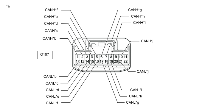
*a Front view of wire harness connector
(to No. 4 CAN Junction Connector)
*b to Multiplex Tilt and Telescopic ECU
(for Sub Bus 1)
*c to No. 9 CAN Junction Connector
(for Sub Bus 1)
*d to Main Body ECU (Multiplex Network Body ECU)
(for Sub Bus 1)
*e to Outer Mirror Control ECU Assembly (for Front Passenger Side)
(for Sub Bus 1)
*f to Headlight Light Control ECU Sub-assembly LH
(for Sub Bus 1)
*g to Position Control ECU and Switch Assembly LH
(for Sub Bus 1)
*h to No. 5 CAN Junction Connector
(for Sub Bus 2)
*i to No. 10 CAN Junction Connector
(for Sub Bus 2)
*j to Clearance Warning ECU Assembly
(for Sub Bus 2)
-
Check the connection diagram of the components which are connected to the No. 4 CAN junction connector.
Terminal No. (Symbol) Wiring Color Connected to O107-1 (CANH) G Multiplex tilt and telescopic ECU
(for Sub bus 1)
O107-12 (CANL) B O107-2 (CANH) L No. 9 CAN junction connector
(for Sub Bus 1)
O107-13 (CANL) B O107-3 (CANH) P Main body ECU (multiplex network body ECU)
(for Sub bus 1)
O107-14 (CANL) B O107-4 (CANH) W Outer mirror control ECU assembly (for front passenger side)
(for Sub bus 1)
O107-15 (CANL) B O107-5 (CANH) V Headlight light control ECU sub-assembly LH
(for Sub bus 1)
O107-16 (CANL) B O107-6 (CANH) R Position control ECU and switch assembly LH
(for Sub bus 1)
O107-17 (CANL) B O107-7 (CANH) L No. 5 CAN junction connector
(for Sub bus 2)
O107-18 (CANL) B O107-8 (CANH) LG No. 10 CAN junction connector
(for Sub bus 2)
O107-19 (CANL) B O107-10 (CANH) SB Clearance warning ECU assembly
(for Sub bus 2)
O107-21 (CANL) B
-
-
-
NO. 5 CAN JUNCTION CONNECTOR (for RHD)
-
Check the No. 5 CAN junction connector.
-
Connection diagram
*a Front view of wire harness connector
(to No. 5 CAN Junction Connector)
*b to Network Gateway ECU
(for Sub Bus 2)
*c to No. 4 CAN Junction Connector
(for Sub Bus 2)
*d to Driving Support ECU Assembly
(w/ Pre-crash Safety System)
(for Sub Bus 2)
*e to Absorber Control ECU
(for Sub Bus 2)
- - -
Check the connection diagram of the components which are connected to the No. 5 CAN junction connector.
Terminal No. (Symbol) Wiring Color Connected to O108-2 (CANH) R Network gateway ECU
(for Sub bus 2)
O108-13 (CANL) B O108-3 (CANH) L No. 4 CAN junction connector
(for Sub bus 2)
O108-14 (CANL) B O108-4 (CANH) G Driving support ECU assembly*
(for Sub bus 2)
O108-15 (CANL) B O108-6 (CANH) SB Absorber control ECU
(for Sub bus 2)
O108-17 (CANL) B
-
*: w/ Pre-crash Safety System
-
-
-
-
NO. 6 CAN JUNCTION CONNECTOR (for RHD)
-
Check the No. 6 CAN junction connector.
-
Connection diagram
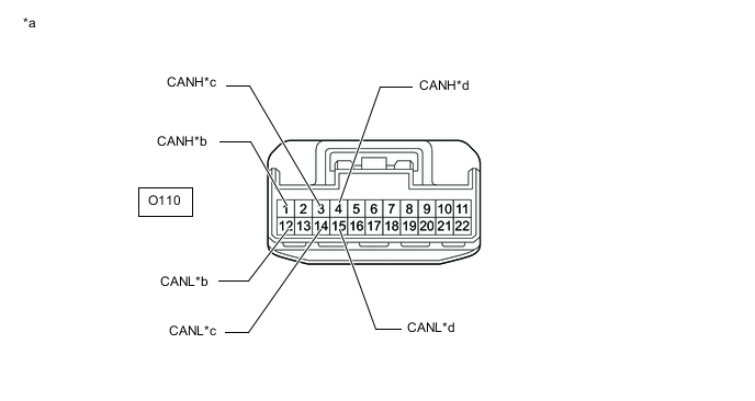
*a Front view of wire harness connector
(to No. 6 CAN Junction Connector)
*b to ECM
(for V3 Bus)
*c to Roll Rate and Vertical Acceleration Sensor
(for V3 Bus)
*d to No. 8 CAN Junction Connector
(for V3 Bus)
-
Check the connection diagram of the components which are connected to the No. 6 CAN junction connector.
Terminal No. (Symbol) Wiring Color Connected to O110-1 (CANH) L ECM
(for V3 bus)
O110-12 (CANL) B O110-3 (CANH) G Roll rate and vertical acceleration sensor
(for V3 bus)
O110-14 (CANL) B O110-4 (CANH) R No. 8 CAN junction connector
(for V3 bus)
O110-15 (CANL) B
-
-
-
NO. 7 CAN JUNCTION CONNECTOR (for RHD)
-
Check the No. 7 CAN junction connector.
-
Connection diagram
*a Front view of wire harness connector
(to No. 7 CAN Junction Connector)
*b to No. 9 CAN Junction Connector
(for Sub Bus 1)
*c to Position Control ECU and Switch Assembly RH
(for Sub Bus 1)
*d to Outer Mirror Control ECU Assembly (for Driver Side)
(for Sub Bus 1)
*e to No. 1 CAN Junction Terminal
(for Sub Bus 1)
- - -
Check the connection diagram of the components which are connected to the No. 7 CAN junction connector.
Terminal No. (Symbol) Wiring Color Connected to T32-7 (CANH) LG No. 9 CAN junction connector
(for Sub bus 1)
T32-18 (CANL) B T32-9 (CANH) R Position control ECU and switch assembly RH
(for Sub bus 1)
T32-20 (CANL) B T32-10 (CANH) W Outer mirror control ECU assembly (for driver side)
(for Sub bus 1)
T32-21 (CANL) B T32-11 (CANH) P No. 1 CAN junction terminal
(for Sub bus 1)
T32-22 (CANL) B
-
-
-
NO. 8 CAN JUNCTION CONNECTOR (for RHD)
-
Check the No. 8 CAN junction connector.
-
Connection diagram

*a Front view of wire harness connector
(to No. 8 CAN Junction Connector)
*b to Torque Vectoring Differential ECU Assembly
(w/ Torque Vectoring Differential System)
(for V3 Bus)
*c to Skid Control ECU (Brake Actuator Assembly)
(for V3 Bus)
*d to No. 6 CAN Junction Connector
(for V3 Bus)
-
Check the connection diagram of the components which are connected to the No. 8 CAN junction connector.
Terminal No. (Symbol) Wiring Color Connected to T44-2 (CANH) V Torque vectoring differential ECU assembly*
(for V3 bus)
T44-13 (CANL) B T44-3 (CANH) LG Skid control ECU (brake actuator assembly)
(for V3 bus)
T44-14 (CANL) B T44-4 (CANH) R No. 6 CAN junction connector
(for V3 bus)
T44-15 (CANL) B
-
*: w/ Torque Vectoring Differential System
-
-
-
-
NO. 9 CAN JUNCTION CONNECTOR (for RHD)
-
Check the No. 9 CAN junction connector.
-
Connection diagram
*a Front view of wire harness connector
(to No. 9 CAN Junction Connector)
*b to No. 10 CAN Junction Connector
(for Sub Bus 2)
*c to No. 2 CAN Junction Terminal
(for Sub Bus 2)
*d to Blind Spot Monitor Sensor LH
(w/ Blind Spot Monitor System)
(for Sub Bus 2)
*e to No. 7 CAN Junction Connector
(for Sub Bus 1)
*f to No. 4 CAN Junction Connector
(for Sub Bus 1)
-
Check the connection diagram of the components which are connected to the No. 9 CAN junction connector.
Terminal No. (Symbol) Wiring Color Connected to U53-1 (CANH) BE No. 10 CAN junction connector
(for Sub bus 2)
U53-12 (CANL) B U53-2 (CANH) V No. 2 CAN junction terminal
(for Sub bus 2)
U53-13 (CANL) B U53-3 (CANH) R Blind spot monitor sensor LH*
(for Sub bus 2)
U53-14 (CANL) B U53-9 (CANH) LG No. 7 CAN junction connector
(for Sub bus 1)
U53-20 (CANL) B U53-10 (CANH) L No. 4 CAN junction connector
(for Sub bus 1)
U53-21 (CANL) B
-
*: w/ Blind Spot Monitor System
-
-
-
-
NO. 10 CAN JUNCTION CONNECTOR (for RHD)
-
Check the No. 10 CAN junction connector.
-
Connection diagram

*a Front view of wire harness connector
(to No. 10 CAN Junction Connector)
*b to No. 4 CAN Junction Connector
(for Sub Bus 2)
*c to No. 9 CAN Junction Connector
(for Sub Bus 2)
*d to Lane Departure Warning Camera
(w/ Lane Departure Alert System)
(for Sub Bus 2)
-
Check the connection diagram of the components which are connected to the No. 10 CAN junction connector.
Terminal No. (Symbol) Wiring Color Connected to W13-1 (CANH) LG No. 4 CAN junction connector
(for Sub bus 2)
W13-7 (CANL) B W13-2 (CANH) BE No. 9 CAN junction connector
(for Sub bus 2)
W13-8 (CANL) B W13-3 (CANH) R Lane departure warning camera*
(for Sub bus 2)
W13-9 (CANL) B
-
*: w/ Lane Departure Alert System
-
-
-
-
NO. 1 CAN JUNCTION TERMINAL
-
Check the No. 1 CAN junction terminal.
-
Connection diagram

*a Front view of wire harness connector
(to No. 1 CAN Junction Terminal)
*b to No. 7 CAN Junction Connector
(for Sub Bus 1)
-
Check the connection diagram of the components which are connected to the No. 1 CAN junction terminal.
Terminal No. (Symbol) Wiring Color Connected to O101-3 (CANH) P No. 7 CAN junction connector
(for Sub bus 1)
O101-2 (CANL) B
-
-
-
NO. 2 CAN JUNCTION TERMINAL
-
Check the No. 2 CAN junction terminal.
-
Connection diagram

*a Front view of wire harness connector
(to No. 2 CAN Junction Terminal)
*b to No. 9 CAN Junction Connector
(for Sub Bus 2)
-
Check the connection diagram of the components which are connected to the No. 2 CAN junction terminal.
Terminal No. (Symbol) Wiring Color Connected to O102-3 (CANH) V No. 9 CAN junction connector
(for Sub bus 2)
O102-2 (CANL) B
-
-
-
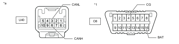
DLC3
-
Disconnect the cable from the negative (-) battery terminal.
-
Measure the resistance according to the value(s) in the table below.
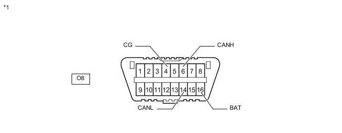
*1 DLC3 - -
-
-
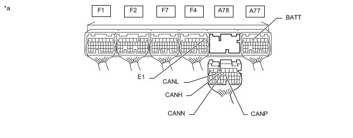
ECM
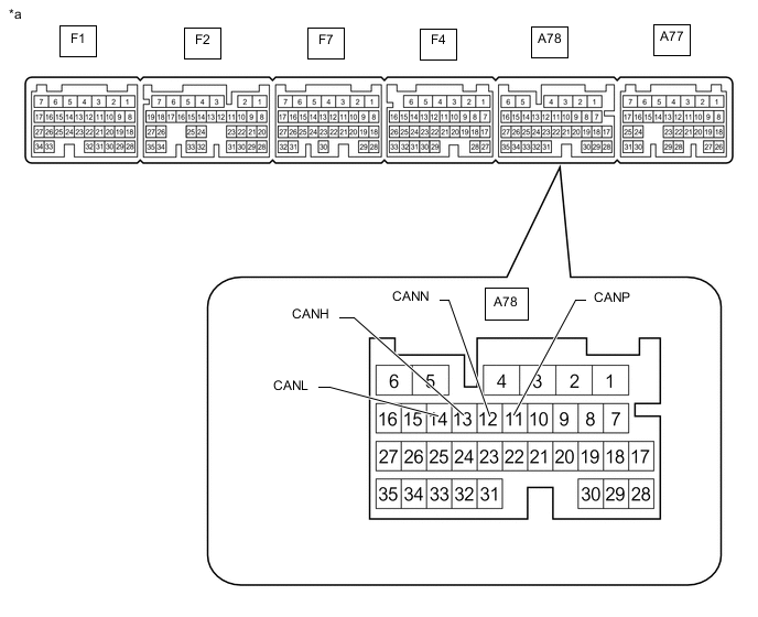
*a Component without harness connected
(ECM)
- -
-
Disconnect the cable from the negative (-) battery terminal.
-
Disconnect the A78 ECM connector.
-
Measure the resistance according to the value(s) in the table below.
*a Rear view of wire harness connector
(to ECM)
- -
-
-
COMBINATION METER ASSEMBLY
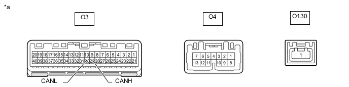
*a Component without harness connected
(Combination Meter Assembly)
- -
-
Disconnect the cable from the negative (-) battery terminal.
-
Disconnect the O3 combination meter assembly connector.
-
Measure the resistance according to the value(s) in the table below.

*a Front view of wire harness connector
(to Combination Meter Assembly)
- -
-
-
INSTRUMENT PANEL JUNCTION BLOCK ASSEMBLY AND MAIN BODY ECU (MULTIPLEX NETWORK BODY ECU)
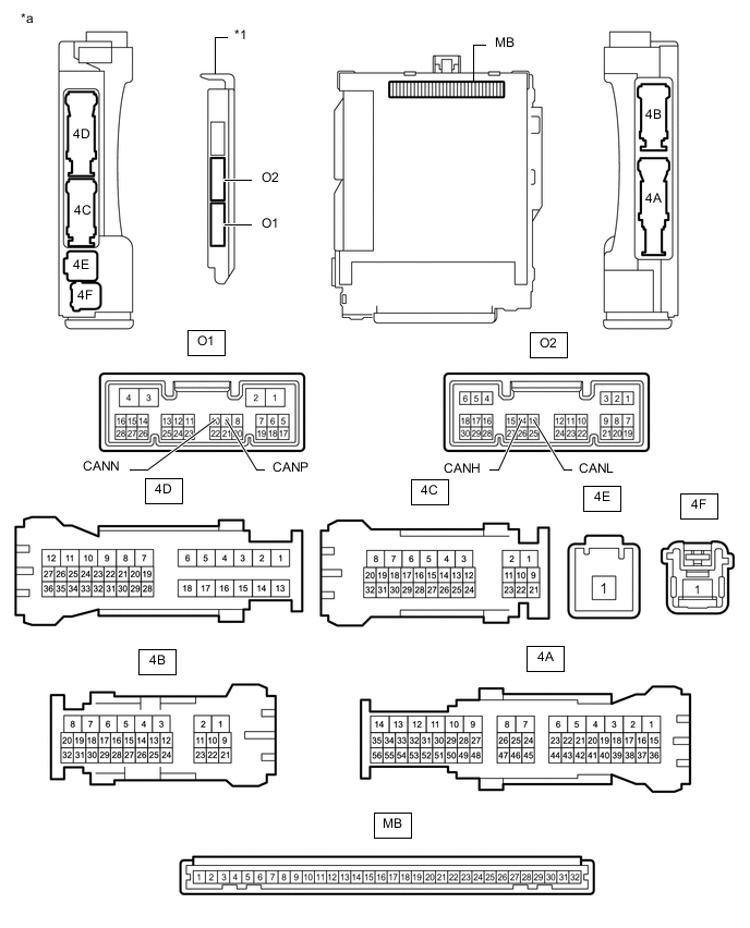
*1 Main Body ECU (Multiplex Network Body ECU) - - *a Component without harness connected
(Instrument Panel Junction Block Assembly and Main Body ECU (Multiplex Network Body ECU))
- -
-
Disconnect the cable from the negative (-) battery terminal.
-
Disconnect the O1 or O2 main body ECU (multiplex network body ECU) connector.
-
Measure the resistance according to the value(s) in the table below.
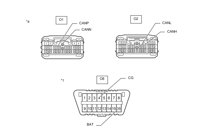
*1 DLC3 - - *a Front view of wire harness connector
(to Main Body ECU (Multiplex Network Body ECU))
- -
-
-
SKID CONTROL ECU (BRAKE ACTUATOR ASSEMBLY)
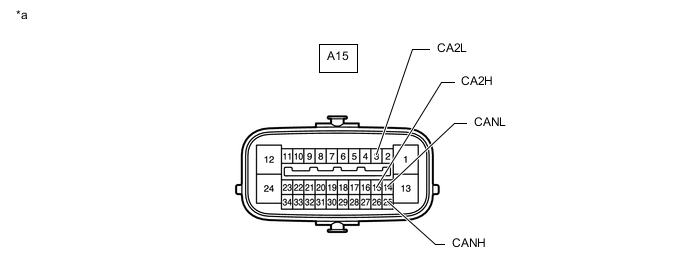
*a Component without harness connected
(Skid Control ECU (Brake Actuator Assembly))
- -
-
Disconnect the cable from the negative (-) battery terminal.
-
Disconnect the A15 skid control ECU (brake actuator assembly) connector.
-
Measure the resistance according to the value(s) in the table below.
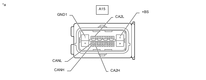
*a Front view of wire harness connector
(to Skid Control ECU (Brake Actuator Assembly))
- -
-
-
STEERING SENSOR
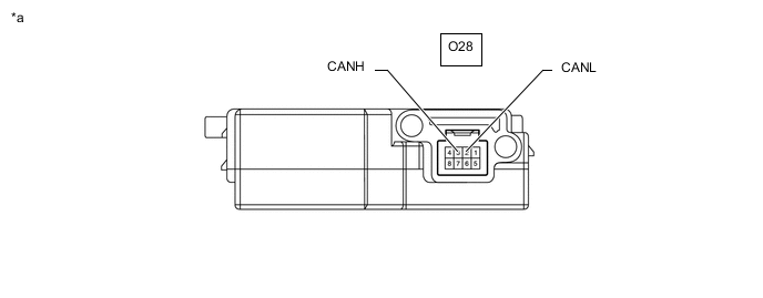
*a Component without harness connected
(Steering Sensor)
- -
-
Disconnect the cable from the negative (-) battery terminal.
-
Disconnect the O28 steering sensor connector.
-
Measure the resistance according to the value(s) in the table below.

*a Front view of wire harness connector
(to Steering Sensor)
- -
-
-
YAW RATE SENSOR

*a Component without harness connected
(Yaw Rate Sensor)
- -
-
Disconnect the cable from the negative (-) battery terminal.
-
Disconnect the O81 yaw rate sensor connector.
-
Measure the resistance according to the value(s) in the table below.

*a Front view of wire harness connector
(to Yaw Rate Sensor)
- -
-
-
POWER STEERING ECU ASSEMBLY
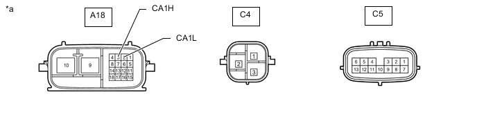
*a Component without harness connected
(Power Steering ECU Assembly)
- -
-
Disconnect the cable from the negative (-) battery terminal.
-
Disconnect the A18 power steering ECU assembly connector.
-
Measure the resistance according to the value(s) in the table below.

*a Front view of wire harness connector
(to Power Steering ECU Assembly)
- -
-
-
AIRBAG ECU ASSEMBLY
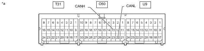
*a Component without harness connected
(Airbag ECU Assembly)
- -
-
Disconnect the cable from the negative (-) battery terminal.
-
Disconnect the O50 airbag ECU assembly connector.
-
Measure the resistance according to the value(s) in the table below.
*1 DLC3 - - *a Front view of wire harness connector
(to Airbag ECU Assembly)
- -
-
-
CERTIFICATION ECU (SMART KEY ECU ASSEMBLY)
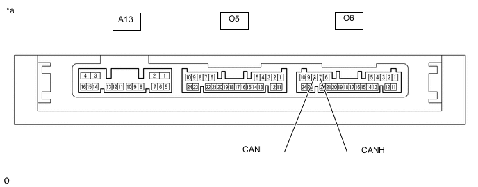
*a Component without harness connected
(Certification ECU (Smart Key ECU Assembly))
- -
-
Disconnect the cable from the negative (-) battery terminal.
-
Disconnect the O6 certification ECU (smart key ECU assembly) connector.
-
Measure the resistance according to the value(s) in the table below.

*a Front view of wire harness connector
(to Certification ECU (Smart Key ECU Assembly))
- -
-
-
RADIO RECEIVER ASSEMBLY (w/ Navigation System)
-
Disconnect the cable from the negative (-) battery terminal.
-
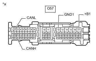
*a Front view of wire harness connector
(to Radio Receiver Assembly)
Disconnect the O57 radio receiver assembly connector.
-
Measure the resistance according to the value(s) in the table below.
-
-
RADIO RECEIVER ASSEMBLY (w/ Audio and Visual System with Remote Touch)
-
Disconnect the cable from the negative (-) battery terminal.
-
*a Front view of wire harness connector
(to Radio Receiver Assembly)
Disconnect the O57 radio receiver assembly connector.
-
Measure the resistance according to the value(s) in the table below.
-
-
RADIO RECEIVER ASSEMBLY (w/ Audio and Visual System without Remote Touch)
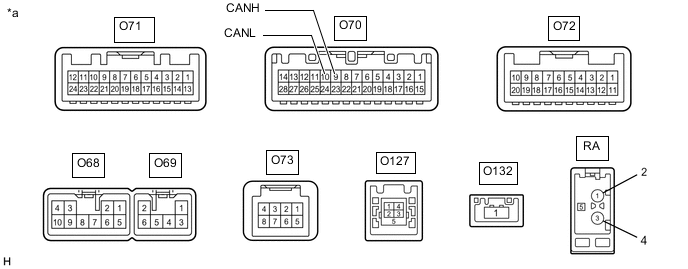
*a Component without harness connected
(Radio Receiver Assembly)
- -
-
Disconnect the cable from the negative (-) battery terminal.
-
Disconnect the O68 and O70 radio receiver assembly connectors.
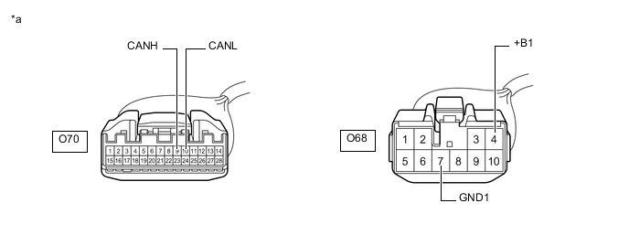
*a Front view of wire harness connector
(to Radio Receiver Assembly)
- - -
Measure the resistance according to the value(s) in the table below.
-
*1: for 6 speaker
-
*2: for 10 speaker
-
-
-
AIR CONDITIONING AMPLIFIER ASSEMBLY
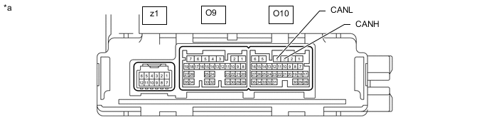
*a Component without harness connected
(Air Conditioning Amplifier Assembly)
- -
-
Disconnect the cable from the negative (-) battery terminal.
-
Disconnect the O9 and O10 air conditioning amplifier assembly connectors.
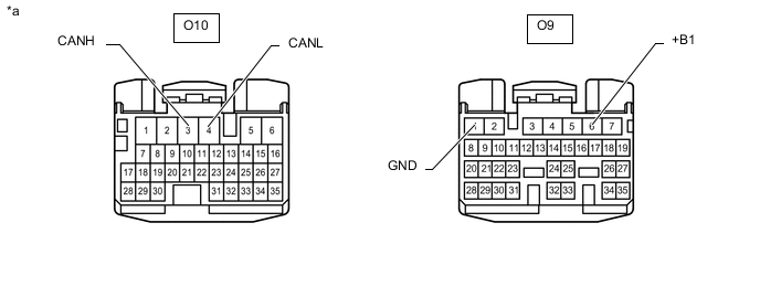
*a Front view of wire harness connector
(to Air Conditioning Amplifier Assembly)
- - -
Measure the resistance according to the value(s) in the table below.
-
-
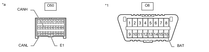
NETWORK GATEWAY ECU
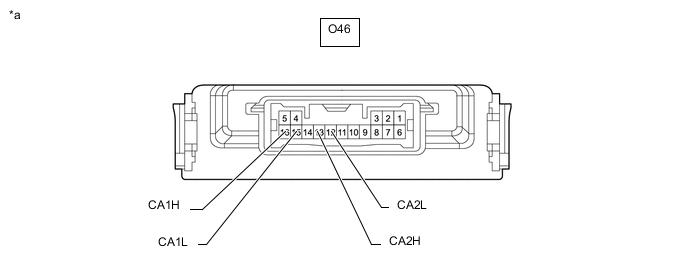
*a Component without harness connected
(Network Gateway ECU)
- -
-
Disconnect the cable from the negative (-) battery terminal.
-
Disconnect the O46 network gateway ECU connector.

*a Front view of wire harness connector
(to Network Gateway ECU)
- - -
Measure the resistance according to the value(s) in the table below.
-
-
TELEMATICS TRANSCEIVER (w/ Telematics Transceiver (for G-BOOK))
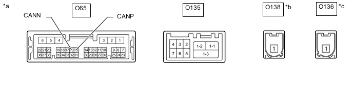
*a Component without harness connected
(Telematics Transceiver)
*b Connector Color: Blue (to Telephone Antenna) *c Connector Color: Gray (to GPS Antenna) - -
-
Disconnect the cable from the negative (-) battery terminal.
-
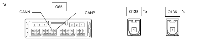
Disconnect the O65 telematics transceiver connector.
-
Measure the resistance according to the value(s) in the table below.

*a Front view of wire harness connector
(to Telematics Transceiver)
- -
-
-
TELEMATICS TRANSCEIVER (w/ Telematics Transceiver (except G-BOOK))
*a Component without harness connected
(Telematics Transceiver)
*b Connector Color: Blue (to Telephone Antenna) *c Connector Color: Gray (to GNSS Antenna) - -
-
Disconnect the cable from the negative (-) battery terminal.
-
Disconnect the O65 telematics transceiver connector.
-
Measure the resistance according to the value(s) in the table below.
*a Front view of wire harness connector
(to Telematics Transceiver)
- -
-
-
HEADLIGHT LIGHT CONTROL ECU SUB-ASSEMBLY LH
*a Component without harness connected
(Headlight Light Control ECU Sub-assembly LH)
- -
-
Disconnect the cable from the negative (-) battery terminal.
-
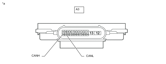
Disconnect the A3 headlight light control ECU sub-assembly LH connector.
-
Measure the resistance according to the value(s) in the table below.
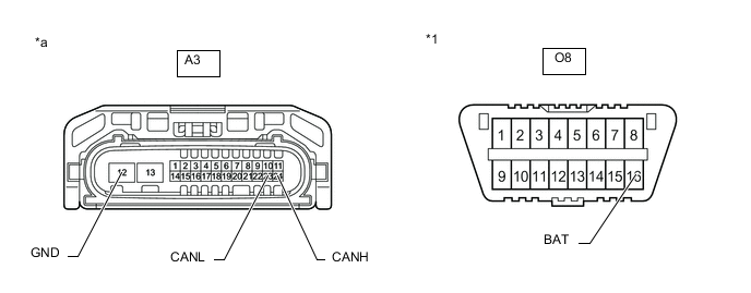
*1 DLC3 - - *a Front view of wire harness connector
(to Headlight Light Control ECU Sub-assembly LH)
- -
-
-
OUTER MIRROR CONTROL ECU ASSEMBLY

*a Component without harness connected
(Outer Mirror Control ECU Assembly (for Driver Side)) (for LHD)
(Outer Mirror Control ECU Assembly (for Front Passenger Side)) (for RHD)
- -
-
Disconnect the cable from the negative (-) battery terminal.
-
Disconnect the S12 outer mirror control ECU assembly connector.

*a Front view of wire harness connector
(to Outer Mirror Control ECU Assembly (for Driver Side)) (for LHD)
(to Outer Mirror Control ECU Assembly (for Front Passenger Side)) (for RHD)
- - -
Measure the resistance according to the value(s) in the table below.
-
-
OUTER MIRROR CONTROL ECU ASSEMBLY

*a Component without harness connected
(Outer Mirror Control ECU Assembly (for Front Passenger Side)) (for LHD)
(Outer Mirror Control ECU Assembly (for Driver Side)) (for RHD)
- -
-
Disconnect the cable from the negative (-) battery terminal.
-
Disconnect the R12 outer mirror control ECU assembly connector.
-
Measure the resistance according to the value(s) in the table below.

*a Front view of wire harness connector
(to Outer Mirror Control ECU Assembly (for Front Passenger Side)) (for LHD)
(to Outer Mirror Control ECU Assembly (for Driver Side)) (for RHD)
- -
-
-
POSITION CONTROL ECU AND SWITCH ASSEMBLY LH

*a Component without harness connected
(Position Control ECU and Switch Assembly LH)
- -
-
Disconnect the cable from the negative (-) battery terminal.
-
Disconnect the b4 and b5 position control ECU and switch assembly LH connectors.
-
Measure the resistance according to the value(s) in the table below.

*a Front view of wire harness connector
(to Position Control ECU and Switch Assembly LH)
- -
-
-
POSITION CONTROL ECU AND SWITCH ASSEMBLY RH

*a Component without harness connected
(Position Control ECU and Switch Assembly RH)
- -
-
Disconnect the cable from the negative (-) battery terminal.
-
Disconnect the a4 and a5 position control ECU and switch assembly RH connectors.
-
Measure the resistance according to the value(s) in the table below.
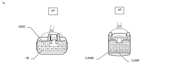
*a Front view of wire harness connector
(to Position Control ECU and Switch Assembly RH)
- -
-
-
MULTIPLEX TILT AND TELESCOPIC ECU

*a Component without harness connected
(Multiplex Tilt and Telescopic ECU)
- -
-
Disconnect the cable from the negative (-) battery terminal.
-
Disconnect the O18 multiplex tilt and telescopic ECU connector.
-
Measure the resistance according to the value(s) in the table below.
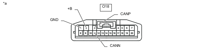
*a Front view of wire harness connector
(to Multiplex Tilt and Telescopic ECU)
- -
-
-
BLIND SPOT MONITOR SENSOR LH (w/ Blind Spot Monitor System)

*a Component without harness connected
(Blind Spot Monitor Sensor LH)
- -
-
Disconnect the cable from the negative (-) battery terminal.
-
Disconnect the U48 blind spot monitor sensor LH connector.
-
Measure the resistance according to the value(s) in the table below.
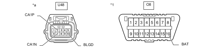
*1 DLC3 - - *a Front view of wire harness connector
(to Blind Spot Monitor Sensor LH)
- -
-
-
DRIVING SUPPORT ECU ASSEMBLY (w/ Pre-crash Safety System)
*a Component without harness connected
(Driving Support ECU Assembly)
- -
-
Disconnect the cable from the negative (-) battery terminal.
-
Disconnect the Q1 driving support ECU assembly connector.
-
Measure the resistance according to the value(s) in the table below.
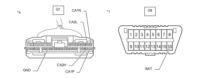
*1 DLC3 - - *a Front view of wire harness connector
(to Driving Support ECU Assembly)
- -
-
-
MILLIMETER WAVE RADAR SENSOR ASSEMBLY (w/ Pre-crash Safety System)

*a Component without harness connected
(Millimeter Wave Radar Sensor Assembly)
- -
-
Disconnect the cable from the negative (-) battery terminal.
-
Disconnect the B7 millimeter wave radar sensor assembly connector.
-
Measure the resistance according to the value(s) in the table below.
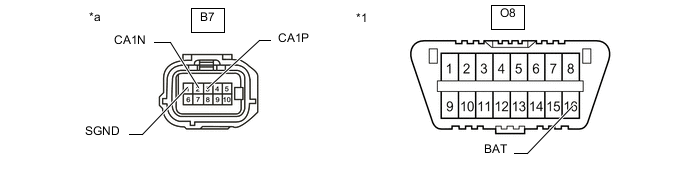
*1 DLC3 - - *a Front view of wire harness connector
(to Millimeter Wave Radar Sensor Assembly)
- -
-
-
OPTION CONNECTOR (BUS BUFFER ECU) (w/ Option Connector)
-
Disconnect the cable from the negative (-) battery terminal.
-
*a Front view of wire harness connector
(to Option Connector (Bus Buffer ECU))
Measure the resistance according to the value(s) in the table below.
-
-
CLEARANCE WARNING ECU ASSEMBLY
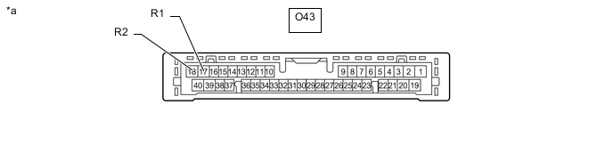
*a Component without harness connected
(Clearance Warning ECU Assembly)
- -
-
Disconnect the cable from the negative (-) battery terminal.
-
Disconnect the O43 clearance warning ECU assembly connector.
-
Measure the resistance according to the value(s) in the table below.
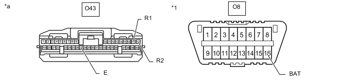
*1 DLC3 - - *a Front view of wire harness connector
(to Clearance Warning ECU Assembly)
- -
-
-
LANE DEPARTURE WARNING CAMERA (w/ Lane Departure Alert System)
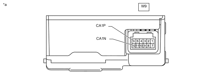
*a Component without harness connected
(Lane Departure Warning Camera)
- -
-
Disconnect the cable from the negative (-) battery terminal.
-
Disconnect the W9 lane departure warning camera connector.
-
Measure the resistance according to the value(s) in the table below.
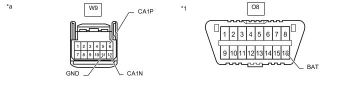
*1 DLC3 - - *a Front view of wire harness connector
(to Lane Departure Warning Camera)
- -
-
-
ROLL RATE AND VERTICAL ACCELERATION SENSOR

*a Component without harness connected
(Roll Rate and Vertical Acceleration Sensor)
- -
-
Disconnect the cable from the negative (-) battery terminal.
-
Disconnect the E1 roll rate and vertical acceleration sensor connector.
-
Measure the resistance according to the value(s) in the table below.
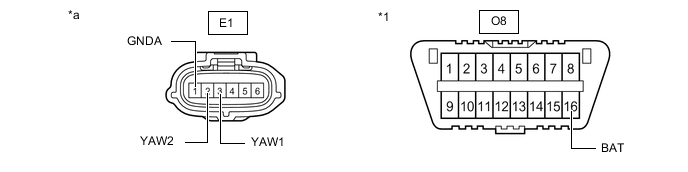
*1 DLC3 - - *a Front view of wire harness connector
(to Roll Rate and Vertical Acceleration Sensor)
- -
-
-
STEREO COMPONENT EQUALIZER ASSEMBLY
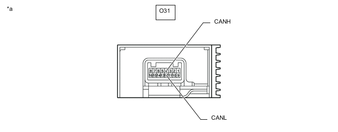
*a Component without harness connected
(Stereo Component Equalizer Assembly)
- -
-
Disconnect the cable from the negative (-) battery terminal.
-
Disconnect the O31 stereo component equalizer assembly connector.
-
Measure the resistance according to the value(s) in the table below.
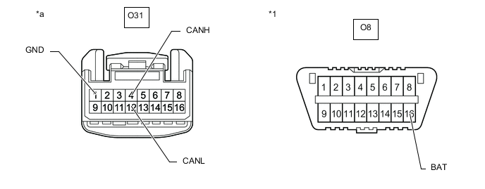
*1 DLC3 - - *a Front view of wire harness connector
(to Stereo Component Equalizer Assembly)
- -
-
-
SPOILER CONTROL ECU ASSEMBLY
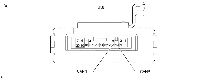
*a Component without harness connected
(Spoiler Control ECU Assembly)
- -
-
Disconnect the cable from the negative (-) battery terminal.
-
Disconnect the U38 spoiler control ECU assembly connector.
-
Measure the resistance according to the value(s) in the table below.
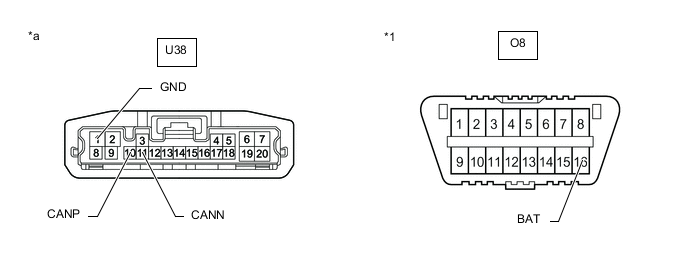
*1 DLC3 - - *a Front view of wire harness connector
(to Spoiler Control ECU Assembly)
- -
-
-
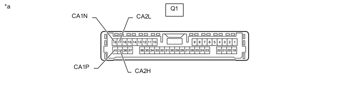
TORQUE VECTORING DIFFERENTIAL ECU ASSEMBLY (w/ Torque Vectoring Differential System)
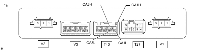
*a Component without harness connected
(Torque Vectoring Differential ECU Assembly)
- -
-
Disconnect the cable from the negative (-) battery terminal.
-
Disconnect the T27 and T43 torque vectoring differential ECU assembly connectors.
-
Measure the resistance according to the value(s) in the table below.
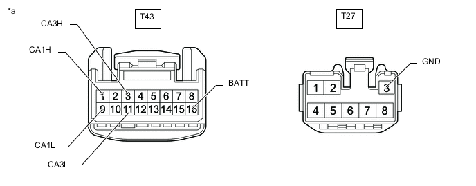
*a Front view of wire harness connector
(to Torque Vectoring Differential ECU Assembly)
- -
-
-
REAR TELEVISION CAMERA ASSEMBLY (w/ Parking Assist Monitor System w/o Parallel Parking Assist Function)
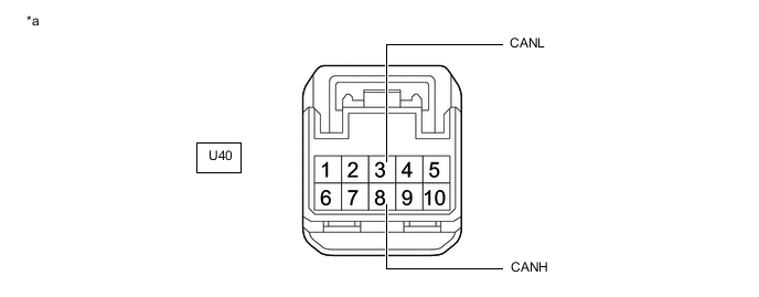
*a Component without harness connected
(Rear Television Camera Assembly)
- -
-
Disconnect the cable from the negative (-) battery terminal.
-
Disconnect the U40 rear television camera assembly connector.
-
Measure the resistance according to the value(s) in the table below.
*1 DLC3 - - *a Front view of wire harness connector
(to Rear Television Camera Assembly)
- -
-
-
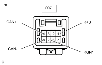
ABSORBER CONTROL ECU
-
Disconnect the cable from the negative (-) battery terminal.
-
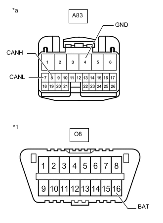
*1 DLC3 *a Front view of wire harness connector
(to Absorber Control ECU)
Disconnect the A83 absorber control ECU connector.
-
Measure the resistance according to the value(s) in the table below.
-