CAN COMMUNICATION SYSTEM SYSTEM DIAGRAM
-
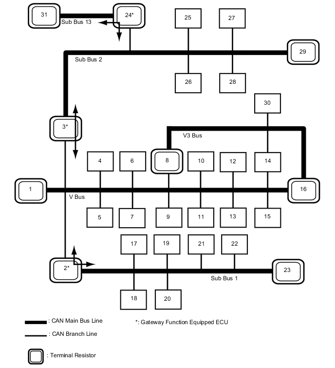
OVERALL CAN BUS DIAGRAM (for LHD)
-
The CAN communication system is composed of 5 buses.
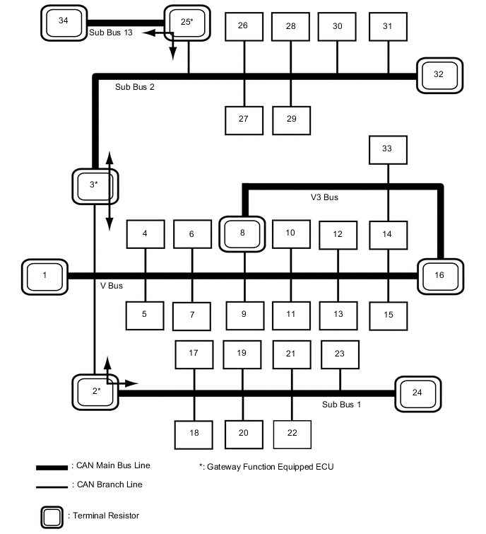
1 Combination Meter Assembly
(for V Bus)
2 Main Body ECU (Multiplex Network Body ECU)
(for V Bus and Sub Bus 1)
3 Network Gateway ECU
(for V Bus and Sub Bus 2)
4 Air Conditioning Amplifier Assembly
(for V Bus)
5 DLC3
(for V Bus)
6 Power Steering ECU Assembly
(for V Bus)
7 Steering Sensor
(for V Bus)
8 Skid Control ECU (Brake Actuator Assembly)
(for V Bus and V3 Bus)
9 Yaw Rate Sensor
(for V Bus)
10 Spoiler Control ECU Assembly
(for V Bus)
11 Airbag ECU Assembly
(for V Bus)
12 Certification ECU (Smart Key ECU Assembly)
(for V Bus)
13 Radio Receiver Assembly
(for V Bus)
14 Torque Vectoring Differential ECU Assembly
(w/ Torque Vectoring Differential System)
(for V Bus and V3 Bus)
15 Stereo Component Equalizer Assembly
(for V Bus)
16 ECM
(for V Bus and V3 Bus)
17 Multiplex Tilt and Telescopic ECU
(for Sub Bus 1)
18 Outer Mirror Control ECU Assembly (for Driver Side)
(for Sub Bus 1)
19 Position Control ECU and Switch Assembly LH
(for Sub Bus 1)
20 Headlight Light Control ECU Sub-assembly LH
(for Sub Bus 1)
21 Position Control ECU and Switch Assembly RH
(for Sub Bus 1)
22 Outer Mirror Control ECU Assembly (for Front Passenger Side)
(for Sub Bus 1)
23 Rear Television Camera Assembly
(w/ Parking Assist Monitor System w/o Parallel Parking Assist Function)
(for Sub Bus 1)
24 No. 1 CAN Junction Terminal
(for Sub Bus 1)
25 Driving Support ECU Assembly
(w/ Pre-crash Safety System)
(for Sub Bus 2 and Sub Bus 13)
26 Telematics Transceiver
(w/ Telematics Transceiver)
(for Sub Bus 2)
27 Clearance Warning ECU Assembly
(for Sub Bus 2)
28 Option Connector (Bus Buffer ECU)
(w/ Option Connector)
(for Sub Bus 2)
29 Lane Departure Warning Camera
(w/ Lane Departure Alert System)
(for Sub Bus 2)
30 Blind Spot Monitor Sensor LH
(w/ Blind Spot Monitor System)
(for Sub Bus 2)
31 Absorber Control ECU
(for Sub Bus 2)
32 No. 2 CAN Junction Terminal
(for Sub Bus 2)
33 Roll Rate and Vertical Acceleration Sensor
(V3 Bus)
34 Millimeter Wave Radar Sensor Assembly
(w/ Pre-crash Safety System)
(for Sub Bus 13)
Tech Tips
-
The main body ECU (multiplex network body ECU) functions as a gateway between the V bus and sub bus 1.
-
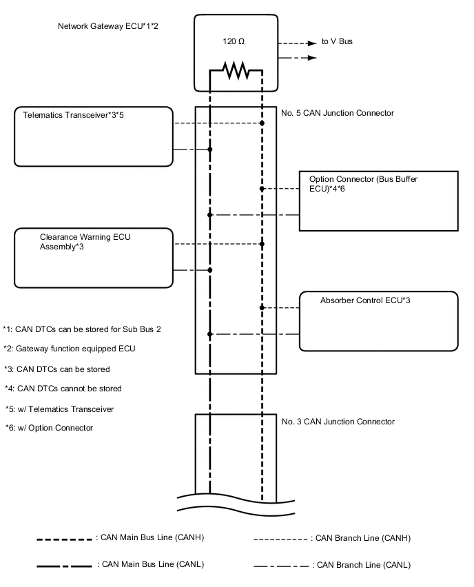
The network gateway ECU functions as a gateway between the V bus and sub bus 2.
-
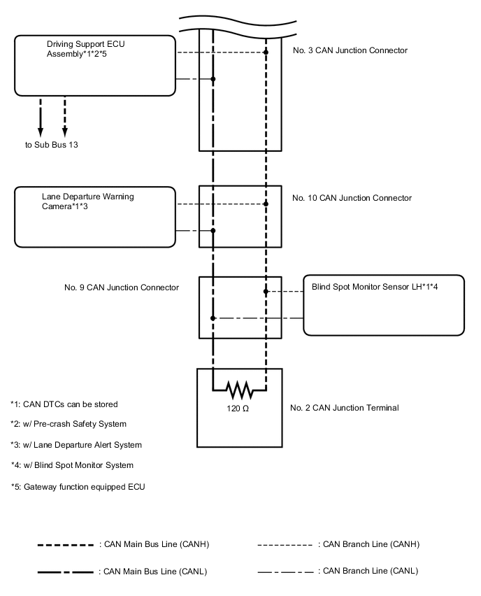
The driving support ECU assembly functions as a gateway between the sub bus 2 and sub bus 13.
-
Refer to the following bus wiring diagrams for details.
-
-
-
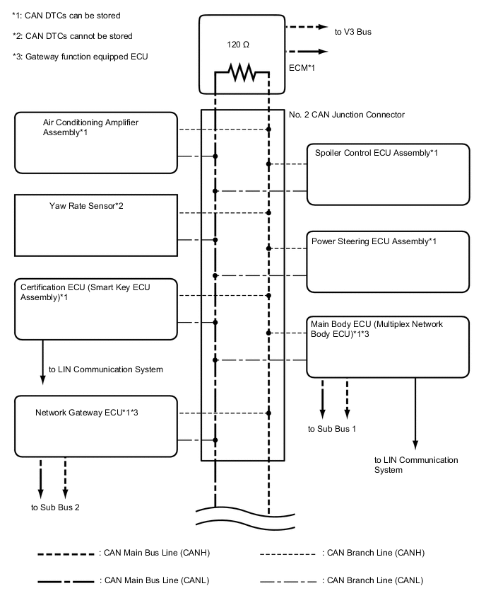
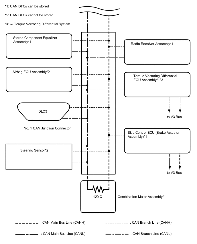
V BUS (for LHD)
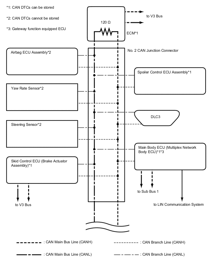
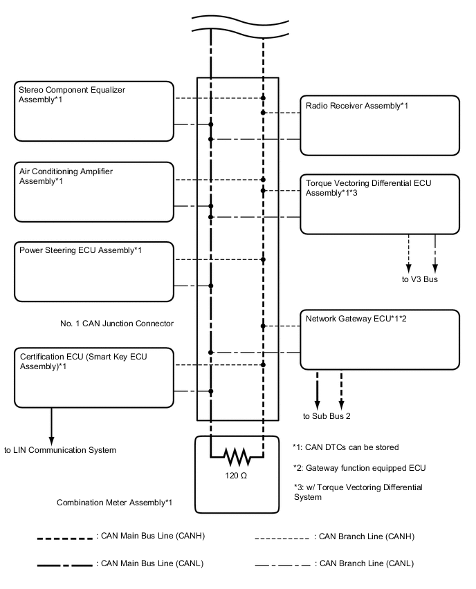
Tech Tips
The CAN communication system connects to other networks via ECUs that function as a gateway.
-
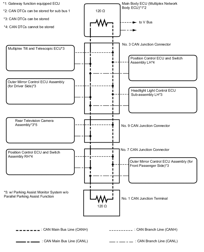
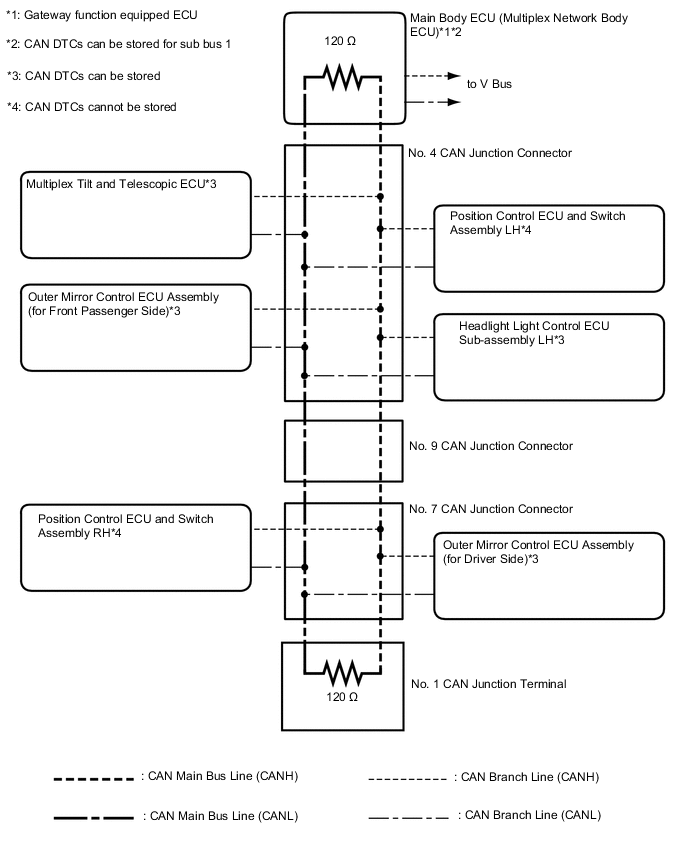
SUB BUS 1 (for LHD)
-
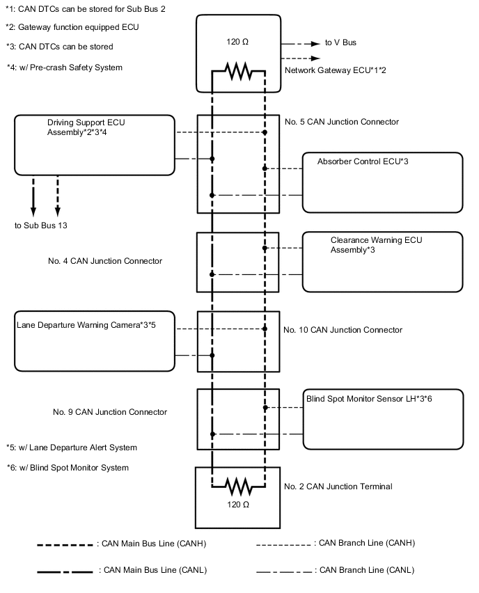
SUB BUS 2 (for LHD)
-
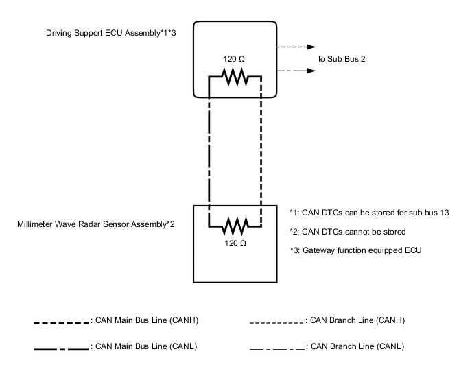
SUB BUS 13 (for LHD with Pre-crash Safety System)
-
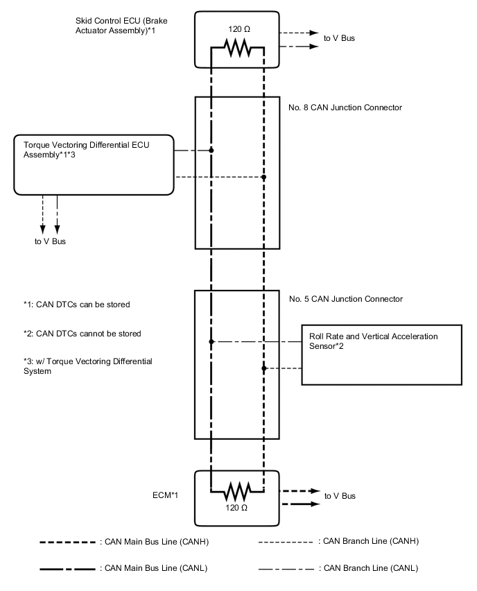
V3 Bus (for LHD)
-
OVERALL CAN BUS DIAGRAM (for RHD)
-
The CAN communication system is composed of 5 buses.
1 Combination Meter Assembly
(for V Bus)
2 Main Body ECU (Multiplex Network Body ECU)
(for V Bus and Sub Bus 1)
3 Network Gateway ECU
(for V Bus and Sub Bus 2)
4 Air Conditioning Amplifier Assembly
(for V Bus)
5 DLC3
(for V Bus)
6 Power Steering ECU Assembly
(for V Bus)
7 Steering Sensor
(for V Bus)
8 Skid Control ECU (Brake Actuator Assembly)
(for V Bus and V3 Bus)
9 Yaw Rate Sensor
(for V Bus)
10 Spoiler Control ECU Assembly
(for V Bus)
11 Airbag ECU Assembly
(for V Bus)
12 Certification ECU (Smart Key ECU Assembly)
(for V Bus)
13 Radio Receiver Assembly
(for V Bus)
14 Torque Vectoring Differential ECU Assembly
(w/ Torque Vectoring Differential System)
(for V Bus and V3 Bus)
15 Stereo Component Equalizer Assembly
(for V Bus)
16 ECM
(for V Bus and V3 Bus)
17 Multiplex Tilt and Telescopic ECU
(for Sub Bus 1)
18 Outer Mirror Control ECU Assembly (for Front Passenger Side)
(for Sub Bus 1)
19 Position Control ECU and Switch Assembly LH
(for Sub Bus 1)
20 Headlight Light Control ECU Sub-assembly LH
(for Sub Bus 1)
21 Position Control ECU and Switch Assembly RH
(for Sub Bus 1)
22 Outer Mirror Control ECU Assembly (for Driver Side)
(for Sub Bus 1)
23 No. 1 CAN Junction Terminal
(for Sub Bus 1)
24 Driving Support ECU Assembly
(w/ Pre-crash Safety System)
(for Sub Bus 2 and Sub Bus 13)
25 Clearance Warning ECU Assembly
(for Sub Bus 2)
26 Lane Departure Warning Camera
(w/ Lane Departure Alert System)
(for Sub Bus 2)
27 Blind Spot Monitor Sensor LH
(w/ Blind Spot Monitor System)
(for Sub Bus 2)
28 Absorber Control ECU
(for Sub Bus 2)
29 No. 2 CAN Junction Terminal
(for Sub Bus 2)
30 Roll Rate and Vertical Acceleration Sensor
(V3 Bus)
31 Millimeter Wave Radar Sensor Assembly
(w/ Pre-crash Safety System)
(for Sub Bus 13)
- - Tech Tips
-
The main body ECU (multiplex network body ECU) functions as a gateway between the V bus and sub bus 1.
-
The network gateway ECU functions as a gateway between the V bus and sub bus 2.
-
The driving support ECU assembly functions as a gateway between the sub bus 2 and sub bus 13.
-
Refer to the following bus wiring diagrams for details.
-
-
-
V BUS (for RHD)
Tech Tips
The CAN communication system connects to other networks via ECUs that function as a gateway.
-
SUB BUS 1 (for RHD)
-
SUB BUS 2 (for RHD)
-
SUB BUS 13 (for RHD with Pre-crash Safety System)
-
V3 Bus (for RHD)
