DESCRIPTION
The seat position airbag sensor circuit consists of the airbag ECU assembly and seat position airbag sensor.
DTC B1653/35 is stored when a malfunction is detected in the seat position airbag sensor circuit.
| DTC No. | Detection Item | DTC Detection Condition | Trouble Area | Test Mode / Check Mode |
|---|---|---|---|---|
| B1653/35 | Seat Position Airbag Sensor Circuit Malfunction |
|
|
Does not apply to test/check mode |
WIRING DIAGRAM
Click here
-
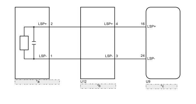
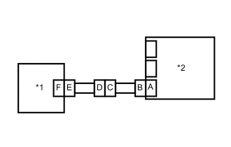
Table 1. *a Seat Position Airbag Sensor *b Front Seat Inner Belt Assembly LH *c Airbag ECU Assembly for LHD:
-
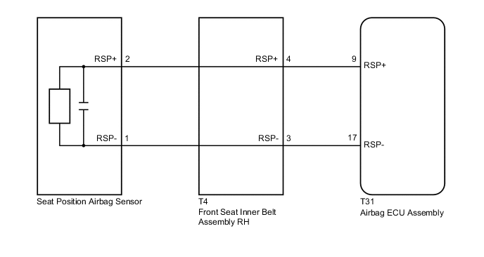
for RHD:
CAUTION / NOTICE / HINT
After turning the engine switch off, waiting time may be required before disconnecting the cable from the negative (-) battery terminal. Therefore, make sure to read the disconnecting the cable from the negative (-) battery terminal notices before proceeding with work.
PROCEDURE
- Click here
CHECK VEHICLE CONDITION
-
Choose the model to be inspected.
Result Result Proceed to LHD A RHD B
-
- Click here
CHECK CONNECTORS
-
Turn the engine switch off.
-
Disconnect the cable from the negative (-) battery terminal.
CAUTION:Wait at least 90 seconds after disconnecting the cable from the negative (-) battery terminal to disable the SRS system.
-
Check that the connectors are properly connected to the airbag ECU assembly, front seat inner belt assembly LH and seat position airbag sensor.
OK The connectors are properly connected. Tip:If the connectors are not properly connected, reconnect the connectors and proceed to the next inspection.
-
Disconnect the connectors from the airbag ECU assembly, front seat inner belt assembly LH and seat position airbag sensor.
-
Check that the terminals of the connectors are not deformed or damaged.
OK The terminals are not deformed or damaged. Result Proceed to OK NG
- OKClick here
- NG
REPLACE WIRE HARNESS
-
- Click here
CHECK SEAT POSITION AIRBAG SENSOR CIRCUIT (OPEN)
-
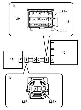
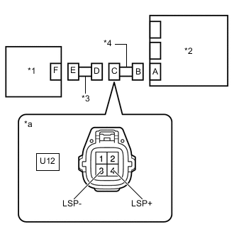
*1 Seat Position Airbag Sensor *2 Airbag ECU Assembly *3 Service Wire *a Front view of wire harness connector
(to Airbag ECU Assembly)
*b Front view of wire harness connector
(to Seat Position Airbag Sensor)
Connect the connectors to the front seat inner belt assembly LH and No. 2 floor wire.
-
Using a service wire, connect terminals 16 (LSP+) and 24 (LSP-) of connector B.
Note:Do not forcibly insert the service wire into the terminals of the connector when connecting the wire.
-
Measure the resistance according to the value(s) in the table below.
Standard Resistance Tester Connection Condition Specified Condition 2 (LSP+) - 1 (LSP-) Always Below 1 Ω Result Proceed to OK NG
- OKClick here
- NGClick here
-
- Click here
CHECK SEAT POSITION AIRBAG SENSOR CIRCUIT (SHORT)
-
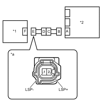
*1 Seat Position Airbag Sensor *2 Airbag ECU Assembly *a Front view of wire harness connector
(to Seat Position Airbag Sensor)
Disconnect the service wire from connector B.
-
Measure the resistance according to the value(s) in the table below.
Standard Resistance Tester Connection Condition Specified Condition 2 (LSP+) - 1 (LSP-) Always 1 MΩ or higher Result Result OK NG
- OKClick here
- NGClick here
-
- Click here
CHECK SEAT POSITION AIRBAG SENSOR CIRCUIT (SHORT TO B+)
-
*1 Seat Position Airbag Sensor *2 Airbag ECU Assembly *a Front view of wire harness connector
(to Seat Position Airbag Sensor)
Connect the cable to the negative (-) battery terminal.
-
Turn the engine switch on (IG).
-
Measure the voltage according to the value(s) in the table below.
Standard Voltage Tester Connection Condition Specified Condition 2 (LSP+) - Body ground Engine switch on (IG) Below 1 V 1 (LSP-) - Body ground Engine switch on (IG) Below 1 V -
Turn the engine switch off.
-
Disconnect the cable from the negative (-) battery terminal.
CAUTION:Wait at least 90 seconds after disconnecting the cable from the negative (-) battery terminal to disable the SRS system.
Result Proceed to OK NG
- OKClick here
- NGClick here
-
- Click here
CHECK SEAT POSITION AIRBAG SENSOR CIRCUIT (SHORT TO GROUND)
-
*1 Seat Position Airbag Sensor *2 Airbag ECU Assembly *a Front view of wire harness connector
(to Seat Position Airbag Sensor)
Measure the resistance according to the value(s) in the table below.
Standard Resistance Tester Connection Condition Specified Condition 2 (LSP+) - Body ground Always 1 MΩ or higher 1 (LSP-) - Body ground Always 1 MΩ or higher Result Proceed to OK NG
- OKClick here
- NGClick here
-
- Click here
CHECK DTC
-
*1 Seat Position Airbag Sensor *2 Airbag ECU Assembly Connect the connectors to the airbag ECU assembly and seat position airbag sensor.
-
Connect the cable to the negative (-) battery terminal.
-
Clear the DTCs stored in memory.
- Body Electrical > SRS Airbag > Clear DTCs
-
-
-
Turn the engine switch off.
-
Turn the engine switch on (IG), and wait for at least 60 seconds.
-
Check for DTCs.
- Body Electrical > SRS Airbag > Trouble Codes
-
-
OK DTC B1653/35 is not output. Tip:Codes other than DTC B1653/35 may be output at this time, but they are not related to this check.
Result Result OK NG
- OK
USE SIMULATION METHOD TO CHECKClick here
- NGClick here
-
- Click here
CHECK SEAT POSITION AIRBAG SENSOR
-
*1 Seat Position Airbag Sensor *2 Airbag ECU Assembly Turn the engine switch off.
-
Disconnect the cable from the negative (-) battery terminal.
CAUTION:Wait at least 90 seconds after disconnecting the cable from the negative (-) battery terminal to disable the SRS system.
-
Replace the seat position airbag sensor with a known good one.
Tip:Perform the following inspection using known good parts from another vehicle if possible.
-
Connect the cable to the negative (-) battery terminal.
-
Clear the DTCs stored in memory.
- Body Electrical > SRS Airbag > Clear DTCs
-
-
-
Turn the engine switch off.
-
Turn the engine switch on (IG), and wait for at least 60 seconds.
-
Check for DTCs.
- Body Electrical > SRS Airbag > Trouble Codes
-
-
OK DTC B1653/35 is not output. Tip:Codes other than DTC B1653/35 may be output at this time, but they are not related to this check.
-
Turn the engine switch off.
-
Disconnect the cable from the negative (-) battery terminal.
CAUTION:Wait at least 90 seconds after disconnecting the cable from the negative (-) battery terminal to disable the SRS system.
-
Restore the seat position airbag sensor that was installed for testing to its original location.
Result Proceed to OK NG
- OK
REPLACE SEAT POSITION AIRBAG SENSORClick here
- NG
REPLACE AIRBAG ECU ASSEMBLYClick here
-
- Click here
CHECK NO. 2 FLOOR WIRE (SHORT TO GROUND)
-
*1 Seat Position Airbag Sensor *2 Airbag ECU Assembly *3 Front Seat Inner Belt Assembly LH *4 No. 2 Floor Wire *a Front view of wire harness connector
(to Front Seat Inner Belt Assembly LH)
Disconnect the No. 2 floor wire from the front seat inner belt assembly LH.
-
Measure the resistance according to the value(s) in the table below.
Standard Resistance Tester Connection Condition Specified Condition U12-4 (LSP+) - Body ground Always 1 MΩ or higher U12-3 (LSP-) - Body ground Always 1 MΩ or higher Result Proceed to OK NG
- OK
REPLACE FRONT SEAT INNER BELT ASSEMBLY LHClick here
- NG
REPLACE NO. 2 FLOOR WIRE
-
- Click here
CHECK NO. 2 FLOOR WIRE (SHORT TO B+)
-
*1 Seat Position Airbag Sensor *2 Airbag ECU Assembly *3 Front Seat Inner Belt Assembly LH *4 No. 2 Floor Wire *a Front view of wire harness connector
(to Front Seat Inner Belt Assembly LH)
Disconnect the No. 2 floor wire from the front seat inner belt assembly LH.
-
Connect the cable to the negative (-) battery terminal.
-
Turn the engine switch on (IG).
-
Measure the voltage according to the value(s) in the table below.
Standard Voltage Tester Connection Condition Specified Condition U12-4 (LSP+) - Body ground Engine switch on (IG) Below 1 V U12-3 (LSP-) - Body ground Engine switch on (IG) Below 1 V Result Proceed to OK NG
- OK
REPLACE FRONT SEAT INNER BELT ASSEMBLY LHClick here
- NG
REPLACE NO. 2 FLOOR WIRE
-
- Click here
CHECK NO. 2 FLOOR WIRE (SHORT)
-
*1 Seat Position Airbag Sensor *2 Airbag ECU Assembly *3 Front Seat Inner Belt Assembly LH *4 No. 2 Floor Wire *a Front view of wire harness connector
(to Front Seat Inner Belt Assembly LH)
Disconnect the No. 2 floor wire from the front seat inner belt assembly LH.
-
Measure the resistance according to the value(s) in the table below.
Standard Resistance Tester Connection Condition Specified Condition U12-4 (LSP+) - U12-3 (LSP-) Always 1 MΩ or higher Result Proceed to OK NG
- OK
REPLACE FRONT SEAT INNER BELT ASSEMBLY LHClick here
- NG
REPLACE NO. 2 FLOOR WIRE
-
- Click here
CHECK NO. 2 FLOOR WIRE (OPEN)
-
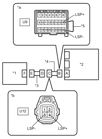
*1 Seat Position Airbag Sensor *2 Airbag ECU Assembly *3 Front Seat Inner Belt Assembly LH *4 No. 2 Floor Wire *5 Service Wire *a Front view of wire harness connector
(to Airbag ECU Assembly)
*b Front view of wire harness connector
(to Front Seat Inner Belt Assembly LH)
Disconnect the No. 2 floor wire from the front seat inner belt assembly LH.
Tip:The service wire has already been inserted into connector B.
-
Measure the resistance according to the value(s) in the table below.
Standard Resistance Tester Connection Condition Specified Condition U12-4 (LSP+) - U12-3 (LSP-) Always Below 1 Ω -
Disconnect the service wire from the connector B.
Result Proceed to OK NG
- OK
REPLACE FRONT SEAT INNER BELT ASSEMBLY LHClick here
- NG
REPLACE NO. 2 FLOOR WIRE
-
- Click here
CHECK CONNECTORS
-
Turn the engine switch off.
-
Disconnect the cable from the negative (-) battery terminal.
CAUTION:Wait at least 90 seconds after disconnecting the cable from the negative (-) battery terminal to disable the SRS system.
-
Check that the connectors are properly connected to the airbag ECU assembly, front seat inner belt assembly RH and seat position airbag sensor.
OK The connectors are properly connected. Tip:If the connectors are not properly connected, reconnect the connectors and proceed to the next inspection.
-
Disconnect the connectors from the airbag ECU assembly, front seat inner belt assembly RH and seat position airbag sensor.
-
Check that the terminals of the connectors are not deformed or damaged.
OK The terminals are not deformed or damaged. Result Proceed to OK NG
- OKClick here
- NG
REPLACE WIRE HARNESS
-
- Click here
CHECK SEAT POSITION AIRBAG SENSOR CIRCUIT (OPEN)
-
*1 Seat Position Airbag Sensor *2 Airbag ECU Assembly *3 Service Wire *a Front view of wire harness connector
(to Airbag ECU Assembly)
*b Front view of wire harness connector
(to Seat Position Airbag Sensor)
Connect the connectors to the front seat inner belt assembly RH and floor wire.
-
Using a service wire, connect terminals 9 (RSP+) and 17 (RSP-) of connector B.
Note:Do not forcibly insert the service wire into the terminals of the connector when connecting the wire.
-
Measure the resistance according to the value(s) in the table below.
Standard Resistance Tester Connection Condition Specified Condition 2 (RSP+) - 1 (RSP-) Always Below 1 Ω Result Proceed to OK NG
- OKClick here
- NGClick here
-
- Click here
CHECK SEAT POSITION AIRBAG SENSOR CIRCUIT (SHORT)
-
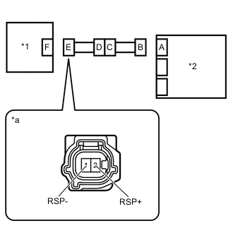
*1 Seat Position Airbag Sensor *2 Airbag ECU Assembly *a Front view of wire harness connector
(to Seat Position Airbag Sensor)
Disconnect the service wire from connector B.
-
Measure the resistance according to the value(s) in the table below.
Standard Resistance Tester Connection Condition Specified Condition 2 (RSP+) - 1 (RSP-) Always 1 MΩ or higher Result Result OK NG
- OKClick here
- NGClick here
-
- Click here
CHECK SEAT POSITION AIRBAG SENSOR CIRCUIT (SHORT TO B+)
-
*1 Seat Position Airbag Sensor *2 Airbag ECU Assembly *a Front view of wire harness connector
(to Seat Position Airbag Sensor)
Connect the cable to the negative (-) battery terminal.
-
Turn the engine switch on (IG).
-
Measure the voltage according to the value(s) in the table below.
Standard Voltage Tester Connection Condition Specified Condition 2 (RSP+) - Body ground Engine switch on (IG) Below 1 V 1 (RSP-) - Body ground Engine switch on (IG) Below 1 V -
Turn the engine switch off.
-
Disconnect the cable from the negative (-) battery terminal.
CAUTION:Wait at least 90 seconds after disconnecting the cable from the negative (-) battery terminal to disable the SRS system.
Result Proceed to OK NG
- OKClick here
- NGClick here
-
- Click here
CHECK SEAT POSITION AIRBAG SENSOR CIRCUIT (SHORT TO GROUND)
-
*1 Seat Position Airbag Sensor *2 Airbag ECU Assembly *a Front view of wire harness connector
(to Seat Position Airbag Sensor)
Measure the resistance according to the value(s) in the table below.
Standard Resistance Tester Connection Condition Specified Condition 2 (RSP+) - Body ground Always 1 MΩ or higher 1 (RSP-) - Body ground Always 1 MΩ or higher Result Proceed to OK NG
- OKClick here
- NGClick here
-
- Click here
CHECK DTC
-
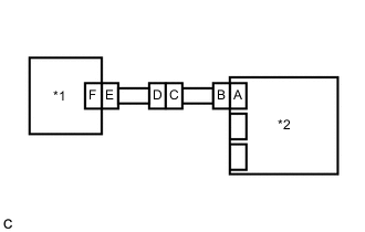
*1 Seat Position Airbag Sensor *2 Airbag ECU Assembly Connect the connectors to the airbag ECU assembly and seat position airbag sensor.
-
Connect the cable to the negative (-) battery terminal.
-
Clear the DTCs stored in memory.
- Body Electrical > SRS Airbag > Clear DTCs
-
-
-
Turn the engine switch off.
-
Turn the engine switch on (IG), and wait for at least 60 seconds.
-
Check for DTCs.
- Body Electrical > SRS Airbag > Trouble Codes
-
-
OK DTC B1653/35 is not output. Tip:Codes other than DTC B1653/35 may be output at this time, but they are not related to this check.
Result Result OK NG
- OK
USE SIMULATION METHOD TO CHECKClick here
- NGClick here
-
- Click here
CHECK SEAT POSITION AIRBAG SENSOR
-
*1 Seat Position Airbag Sensor *2 Airbag ECU Assembly Turn the engine switch off.
-
Disconnect the cable from the negative (-) battery terminal.
CAUTION:Wait at least 90 seconds after disconnecting the cable from the negative (-) battery terminal to disable the SRS system.
-
Replace the seat position airbag sensor with a known good one.
Tip:Perform the following inspection using known good parts from another vehicle if possible.
-
Connect the cable to the negative (-) battery terminal.
-
Clear the DTCs stored in memory.
- Body Electrical > SRS Airbag > Clear DTCs
-
-
-
Turn the engine switch off.
-
Turn the engine switch on (IG), and wait for at least 60 seconds.
-
Check for DTCs.
- Body Electrical > SRS Airbag > Trouble Codes
-
-
OK DTC B1653/35 is not output. Tip:Codes other than DTC B1653/35 may be output at this time, but they are not related to this check.
-
Turn the engine switch off.
-
Disconnect the cable from the negative (-) battery terminal.
CAUTION:Wait at least 90 seconds after disconnecting the cable from the negative (-) battery terminal to disable the SRS system.
-
Restore the seat position airbag sensor that was installed for testing to its original location.
Result Proceed to OK NG
- OK
REPLACE SEAT POSITION AIRBAG SENSORClick here
- NG
REPLACE AIRBAG ECU ASSEMBLYClick here
-
- Click here
CHECK FLOOR WIRE (SHORT TO GROUND)
-
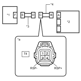
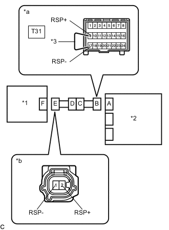
*1 Seat Position Airbag Sensor *2 Airbag ECU Assembly *3 Front Seat Inner Belt Assembly RH *4 Floor Wire *a Front view of wire harness connector
(to Front Seat Inner Belt Assembly RH)
Disconnect the floor wire from the front seat inner belt assembly RH.
-
Measure the resistance according to the value(s) in the table below.
Standard Resistance Tester Connection Condition Specified Condition T4-4 (RSP+) - Body ground Always 1 MΩ or higher T4-3 (RSP-) - Body ground Always 1 MΩ or higher Result Proceed to OK NG
- OK
REPLACE FRONT SEAT INNER BELT ASSEMBLY RHClick here
- NG
REPLACE FLOOR WIRE
-
- Click here
CHECK FLOOR WIRE (SHORT TO B+)
-
*1 Seat Position Airbag Sensor *2 Airbag ECU Assembly *3 Front Seat Inner Belt Assembly RH *4 Floor Wire *a Front view of wire harness connector
(to Front Seat Inner Belt Assembly RH)
Disconnect the floor wire from the front seat inner belt assembly RH.
-
Connect the cable to the negative (-) battery terminal.
-
Turn the engine switch on (IG).
-
Measure the voltage according to the value(s) in the table below.
Standard Voltage Tester Connection Condition Specified Condition T4-4 (RSP+) - Body ground Engine switch on (IG) Below 1 V T4-3 (RSP-) - Body ground Engine switch on (IG) Below 1 V Result Proceed to OK NG
- OK
REPLACE FRONT SEAT INNER BELT ASSEMBLY RHClick here
- NG
REPLACE FLOOR WIRE
-
- Click here
CHECK FLOOR WIRE (SHORT)
-
*1 Seat Position Airbag Sensor *2 Airbag ECU Assembly *3 Front Seat Inner Belt Assembly RH *4 Floor Wire *a Front view of wire harness connector
(to Front Seat Inner Belt Assembly RH)
Disconnect the floor wire from the front seat inner belt assembly RH.
-
Measure the resistance according to the value(s) in the table below.
Standard Resistance Tester Connection Condition Specified Condition T4-4 (RSP+) - T4-3 (RSP-) Always 1 MΩ or higher Result Proceed to OK NG
- OK
REPLACE FRONT SEAT INNER BELT ASSEMBLY RHClick here
- NG
REPLACE FLOOR WIRE
-
- Click here
CHECK FLOOR WIRE (OPEN)
-
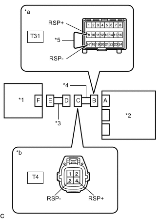
*1 Seat Position Airbag Sensor *2 Airbag ECU Assembly *3 Front Seat Inner Belt Assembly RH *4 Floor Wire *5 Service Wire *a Front view of wire harness connector
(to Airbag ECU Assembly)
*b Front view of wire harness connector
(to Front Seat Inner Belt Assembly RH)
Disconnect the floor wire from the front seat inner belt assembly RH.
Tip:The service wire has already been inserted into connector B.
-
Measure the resistance according to the value(s) in the table below.
Standard Resistance Tester Connection Condition Specified Condition T4-4 (RSP+) - T4-3 (RSP-) Always Below 1 Ω -
Disconnect the service wire from the connector B.
Result Proceed to OK NG
- OK
REPLACE FRONT SEAT INNER BELT ASSEMBLY RHClick here
- NG
REPLACE FLOOR WIRE
-