METER / GAUGE SYSTEM Tachometer Malfunction
DESCRIPTION
In this circuit, the combination meter assembly receives engine speed signals from the ECM via CAN communication. The combination meter assembly displays the engine speed calculated based on the data received from the ECM.
WIRING DIAGRAM
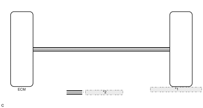
| *1 | Combination Meter Assembly (Meter Circuit Plate) |
| *2 | CAN Communication Line |
CAUTION / NOTICE / HINT
Note
Before replacing the ECM, refer to Service Bulletin.
PROCEDURE
-
CHECK CAN COMMUNICATION SYSTEM
-
Check if CAN communication DTCs are output.
Result Result Proceed to CAN communication DTCs are not output. A CAN communication DTCs are output. B
B 
GO TO CAN COMMUNICATION SYSTEM Click here
A 
-
-
READ VALUE USING GTS (ENGINE RPM)
-
Connect the GTS to the DLC3.
-
Turn the engine switch on (IG).
-
Turn the GTS on.
-
Enter the following menus: Body Electrical / Combination Meter / Data List.
-
Read the Data List according to the display on the GTS.
Body Electrical > Combination Meter > Data ListTester Display Measurement Item Range Normal Condition Diagnostic Note Engine Rpm Engine speed Min.: 0 rpm, Max.: 12750 rpm Almost the same as actual tachometer -
Body Electrical > Combination Meter > Data ListTester Display Engine Rpm OK Engine speed displayed on the GTS is almost the same as the tachometer indication. Tech Tips
-
When the Data List values and tachometer values match, a signal output malfunction of the ECM or an internal malfunction of the combination meter assembly is suspected.
-
When the Data List values and tachometer values do not match, an internal malfunction of the combination meter assembly is suspected.
Result Proceed to OK NG -
NG
REPLACE COMBINATION METER ASSEMBLY Click here
OK
-
-
CHECK FOR DTC
-
Check if SFI system DTCs are output.
SFI system (w/ Canistor Pump Module): Click here
SFI system (w/o Canistor Pump Module): Click here
Powertrain > Engine > Trouble CodesResult Result Proceed to SFI system DTCs are not output. A SFI system DTCs are output. B
B
GO TO SFI SYSTEM SFI system (w/ Canister Pump Module): Click here
GO TO SFI SYSTEM SFI system (w/o Canister Pump Module): Click hereA
-
-
READ VALUE USING GTS (ENGINE SPEED, ENGINE RPM)
-
Connect the GTS to the DLC3.
-
Turn the engine switch on (IG).
-
Turn the GTS on.
-
Enter the following menus:
-
for Engine: Powertrain / Engine / Data List.
-
for Combination Meter: Body Electrical / Combination Meter / Data List.
-
-
Read the Data List according to the display on the GTS.
-
Engine
Powertrain > Engine > Data ListTester Display Measurement Item Range Normal Condition Reference Value Diagnostic Note Engine Speed Engine speed Min.: 0 rpm, Max.: 16383 rpm 700 to 800 rpm: Idling with warm engine Idling (engine warmed up and A/C off): 763 rpm When the crankshaft position sensor is malfunctioning, "Engine Speed" is approximately 0 rpm or varies greatly from the actual engine speed.
Powertrain > Engine > Data ListTester Display Engine Speed -
Combination Meter
Body Electrical > Combination Meter > Data ListTester Display Measurement Item Range Normal Condition Diagnostic Note Engine Rpm Engine speed Min.: 0 rpm, Max.: 12750 rpm Almost the same as actual tachometer -
Body Electrical > Combination Meter > Data ListTester Display Engine Rpm
Result Result Proceed to The Data List values of the ECUs do not match. A The Data List values of the ECUs match. B Tech Tips
-
When the Data List values of the ECUs match, an internal malfunction of the ECM is suspected.
-
When the Data List values of the ECUs do not match, a signal output malfunction of the ECM or an internal malfunction of the combination meter assembly is suspected.
-
B
REPLACE ECM Click here
A
-
-
REPLACE COMBINATION METER ASSEMBLY
-
Replace the combination meter assembly with a new or known good one.
OK The operation of the tachometer returns to normal. Result Proceed to OK NG
OK
END
NG
REPLACE ECM Click here
-