NAVIGATION SYSTEM, Diagnostic DTC:B15C3
| DTC Code | DTC Name |
|---|---|
| B15C3 | Speaker Output Short |
DESCRIPTION
This DTC is stored when a malfunction occurs in the speakers.
| DTC No. | Detection Item | DTC Detection Condition | Trouble Area |
|---|---|---|---|
| B15C3 | Speaker Output Short | A short is detected in the speaker output circuit. |
|
*: w/ Manual (SOS) Switch
WIRING DIAGRAM
-
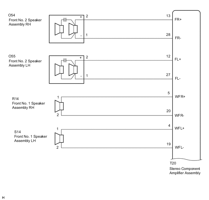
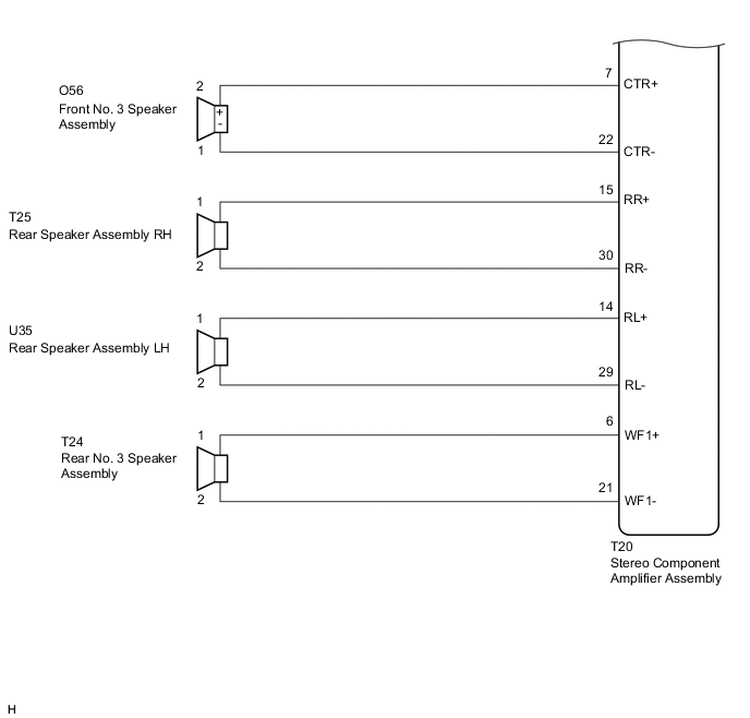
for 10 Speakers
-
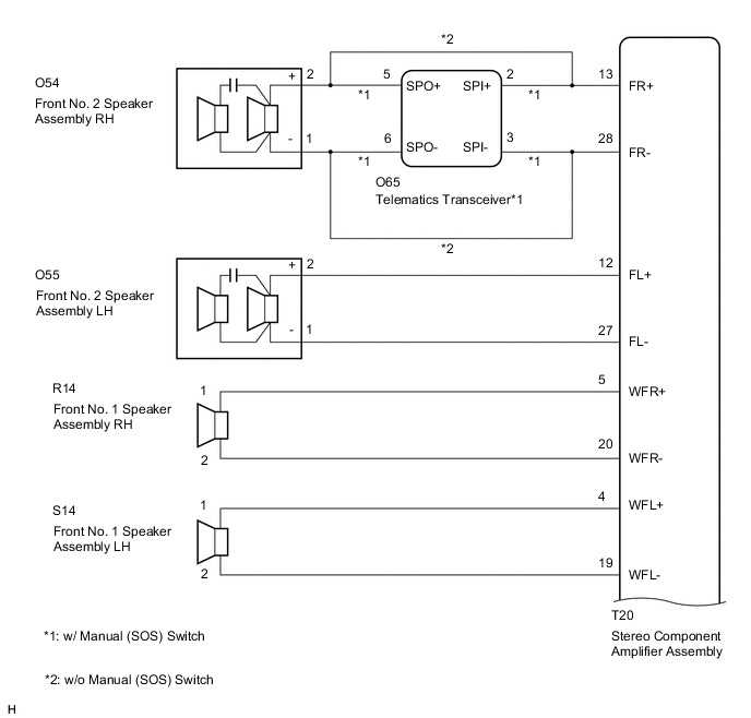
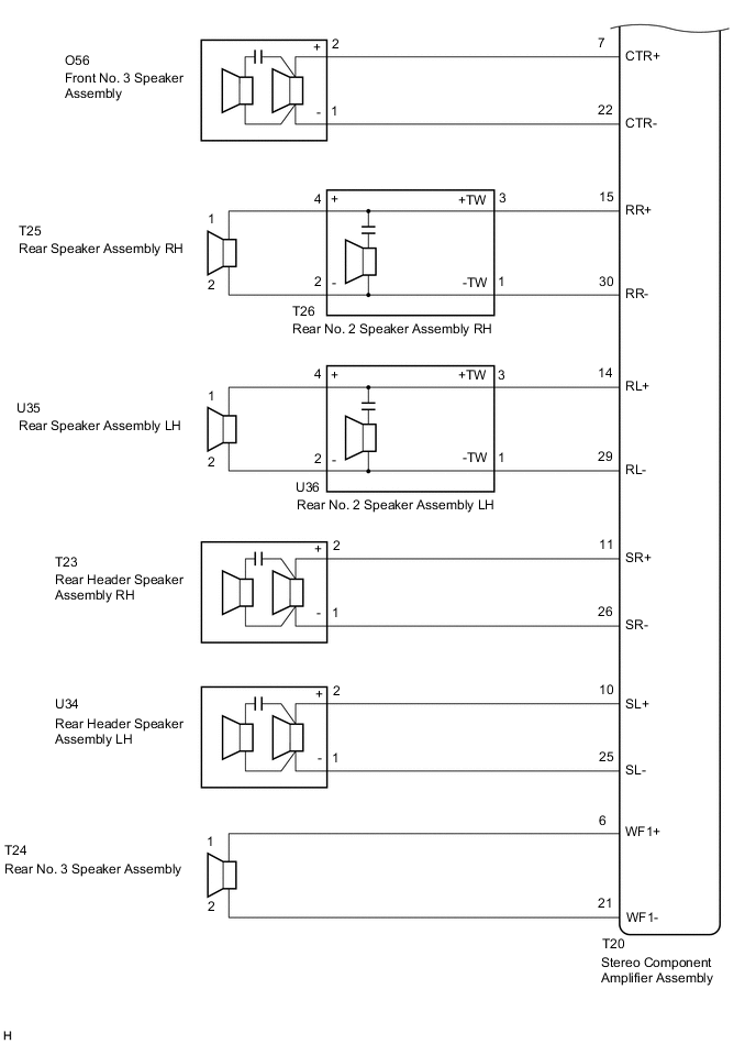
for 17 Speakers
CAUTION / NOTICE / HINT
Note
Depending on the parts that are replaced during vehicle inspection or maintenance, performing initialization, registration or calibration may be needed. Refer to Precaution for Navigation System.
PROCEDURE
-
CHECK MODEL
-
Choose the model to be inspected.
Result Result Proceed to for 10 Speakers A for 17 Speakers (w/ Manual (SOS) Switch) B for 17 Speakers (w/o Manual (SOS) Switch) C
B 
CHECK HARNESS AND CONNECTOR (STEREO COMPONENT AMPLIFIER ASSEMBLY - BODY GROUND) Click here
C
CHECK HARNESS AND CONNECTOR (STEREO COMPONENT AMPLIFIER ASSEMBLY - BODY GROUND) Click here
A 
-
-
CHECK HARNESS AND CONNECTOR (STEREO COMPONENT AMPLIFIER ASSEMBLY - BODY GROUND)
-
Disconnect the T20 stereo component amplifier assembly connector.
-
Disconnect the O54 and O55 front No. 2 speaker assembly connectors.
-
Disconnect the R14 and S14 front No. 1 speaker assembly connectors.
-
Disconnect the O56 front No. 3 speaker assembly connector.
-
Disconnect the T25 and U35 rear speaker assembly connectors.
-
Disconnect the T24 rear No. 3 speaker assembly connector.
-
Measure the resistance between the stereo component amplifier assembly and body ground to check for a short circuit in the wire harness.
Standard Resistance Tester Connection Condition Specified Condition T20-13 (FR+) - Body ground Always 10 kΩ or higher T20-28 (FR-) - Body ground Always 10 kΩ or higher T20-12 (FL+) - Body ground Always 10 kΩ or higher T20-27 (FL-) - Body ground Always 10 kΩ or higher T20-5 (WFR+) - Body ground Always 10 kΩ or higher T20-20 (WFR-) - Body ground Always 10 kΩ or higher T20-4 (WFL+) - Body ground Always 10 kΩ or higher T20-19 (WFL-) - Body ground Always 10 kΩ or higher T20-7 (CTR+) - Body ground Always 10 kΩ or higher T20-22 (CTR-) - Body ground Always 10 kΩ or higher T20-15 (RR+) - Body ground Always 10 kΩ or higher T20-30 (RR-) - Body ground Always 10 kΩ or higher T20-14 (RL+) - Body ground Always 10 kΩ or higher T20-29 (RL-) - Body ground Always 10 kΩ or higher T20-6 (WF1+) - Body ground Always 10 kΩ or higher T20-21 (WF1-) - Body ground Always 10 kΩ or higher Result Proceed to OK NG
NG 
REPAIR OR REPLACE HARNESS OR CONNECTOR
OK
-
-
INSPECT FRONT NO. 2 SPEAKER ASSEMBLY
-
Remove the front No. 2 speaker assembly.
-
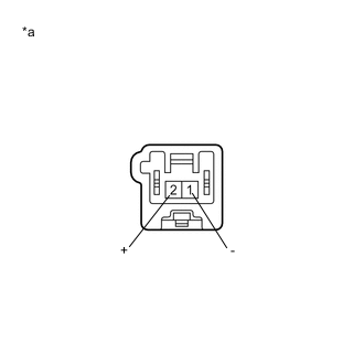
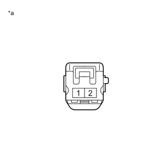
*a Component without harness connected
(Front No. 2 Speaker Assembly)
Measure the resistance according to the value(s) in the table below.
Standard Resistance Tester Connection Condition Specified Condition 1 (-) - 2 (+) Always 3.2 to 4.8 Ω Result Proceed to OK NG
NG
REPLACE FRONT NO. 2 SPEAKER ASSEMBLY Click here
OK
-
-
REPLACE FRONT NO. 2 SPEAKER ASSEMBLY
-
Replace the front No. 2 speaker assembly with a new or known good one.
-
Clear the DTCs.
Body Electrical > Navigation System > Clear DTCs -
Recheck for DTCs and check that no DTCs are output.
Body Electrical > Navigation System > Trouble CodesOK No DTCs are output. Tech Tips
-
Connect all the connectors to the front No. 2 speaker assemblies that were disconnected.
-
When there is a possibility that either the right or left front No. 2 speaker assembly is defective, inspect by interchanging the right one with the left one.
-
Perform the above inspection on both the LH and RH side.
Result Proceed to OK NG -
OK
END
NG
-
-
INSPECT FRONT NO. 1 SPEAKER ASSEMBLY
-
Remove the front No. 1 speaker assembly.
-
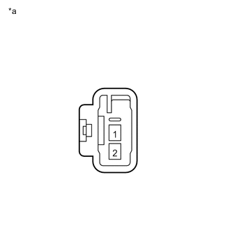
*a Component without harness connected
(Front No. 1 Speaker Assembly)
Measure the resistance according to the value(s) in the table below.
Standard Resistance Tester Connection Condition Specified Condition 1 - 2 Always 3.2 to 4.8 Ω Result Proceed to OK NG
NG
REPLACE FRONT NO. 1 SPEAKER ASSEMBLY Click here
OK
-
-
INSPECT FRONT NO. 3 SPEAKER ASSEMBLY
-
Remove the front No. 3 speaker assembly.
-
*a Component without harness connected
(Front No. 3 Speaker Assembly)
Measure the resistance according to the value(s) in the table below.
Standard Resistance Tester Connection Condition Specified Condition 1 (-) - 2 (+) Always 4.0 to 6.0 Ω Result Proceed to OK NG
NG
REPLACE FRONT NO. 3 SPEAKER ASSEMBLY Click here
OK
-
-
INSPECT REAR SPEAKER ASSEMBLY
-
Remove the rear speaker assembly.
-
*a Component without harness connected
(Rear Speaker Assembly)
Measure the resistance according to the value(s) in the table below.
Standard Resistance Tester Connection Condition Specified Condition 1 - 2 Always 3.2 to 4.8 Ω Result Proceed to OK NG
NG
REPLACE REAR SPEAKER ASSEMBLY Click here
OK
-
-
INSPECT REAR NO. 3 SPEAKER ASSEMBLY
-
Remove the rear No. 3 speaker assembly.
-
*a Component without harness connected
(Rear No. 3 Speaker Assembly)
Measure the resistance according to the value(s) in the table below.
Standard Resistance Tester Connection Condition Specified Condition 1 - 2 Always 2.0 to 3.0 Ω Result Proceed to OK NG
OK
REPLACE STEREO COMPONENT AMPLIFIER ASSEMBLY Click here
NG
REPLACE REAR NO. 3 SPEAKER ASSEMBLY Click here
-
-
CHECK HARNESS AND CONNECTOR (STEREO COMPONENT AMPLIFIER ASSEMBLY - BODY GROUND)
-
Disconnect the T20 stereo component amplifier assembly connector.
-
Disconnect the O65 telematics transceiver connector.
-
Disconnect the O55 front No. 2 speaker assembly LH connector.
-
Disconnect the R14 and S14 front No. 1 speaker assembly connectors.
-
Disconnect the O56 front No. 3 speaker assembly connector.
-
Disconnect the T26 and U36 rear No. 2 speaker assembly connectors.
-
Disconnect the T23 and U34 rear header speaker assembly connectors.
-
Disconnect the T24 rear No. 3 speaker assembly connector.
-
Measure the resistance between the stereo component amplifier assembly and body ground to check for a short circuit in the wire harness.
Standard Resistance Tester Connection Condition Specified Condition T20-13 (FR+) - Body ground Always 10 kΩ or higher T20-28 (FR-) - Body ground Always 10 kΩ or higher T20-12 (FL+) - Body ground Always 10 kΩ or higher T20-27 (FL-) - Body ground Always 10 kΩ or higher T20-5 (WFR+) - Body ground Always 10 kΩ or higher T20-20 (WFR-) - Body ground Always 10 kΩ or higher T20-4 (WFL+) - Body ground Always 10 kΩ or higher T20-19 (WFL-) - Body ground Always 10 kΩ or higher T20-7 (CTR+) - Body ground Always 10 kΩ or higher T20-22 (CTR-) - Body ground Always 10 kΩ or higher T20-15 (RR+) - Body ground Always 10 kΩ or higher T20-30 (RR-) - Body ground Always 10 kΩ or higher T20-14 (RL+) - Body ground Always 10 kΩ or higher T20-29 (RL-) - Body ground Always 10 kΩ or higher T20-11 (SR+) - Body ground Always 10 kΩ or higher T20-26 (SR-) - Body ground Always 10 kΩ or higher T20-10 (SL+) - Body ground Always 10 kΩ or higher T20-25 (SL-) - Body ground Always 10 kΩ or higher T20-6 (WF1+) - Body ground Always 10 kΩ or higher T20-21 (WF1-) - Body ground Always 10 kΩ or higher Result Proceed to OK NG
NG
REPAIR OR REPLACE HARNESS OR CONNECTOR
OK
-
-
CHECK HARNESS AND CONNECTOR (TELEMATICS TRANSCEIVER - BODY GROUND)
-
Disconnect the O65 telematics transceiver connector.
-
Disconnect the O54 front No. 2 speaker assembly RH connector.
-
Measure the resistance between the telematics transceiver and body ground to check for a short circuit in the wire harness.
Standard Resistance Tester Connection Condition Specified Condition O65-5 (SPO+) - Body ground Always 10 kΩ or higher O65-6 (SPO-) - Body ground Always 10 kΩ or higher Result Proceed to OK NG
NG
REPAIR OR REPLACE HARNESS OR CONNECTOR
OK
-
-
CHECK HARNESS AND CONNECTOR (REAR NO. 2 SPEAKER ASSEMBLY - BODY GROUND)
-
Disconnect the T25 and U35 rear speaker assembly connectors.
-
Disconnect the T26 and U36 rear No. 2 speaker assembly connectors.
-
Measure the resistance between each of the rear No. 2 speaker assemblies and body ground to check for a short circuit in the wire harness.
Standard Resistance Tester Connection Condition Specified Condition T26-4 (+) - Body ground Always 10 kΩ or higher T26-2 (-) - Body ground Always 10 kΩ or higher U36-4 (+) - Body ground Always 10 kΩ or higher U36-2 (-) - Body ground Always 10 kΩ or higher Result Proceed to OK NG
NG
REPAIR OR REPLACE HARNESS OR CONNECTOR
OK
-
-
INSPECT TELEMATICS TRANSCEIVER
-
Remove the telematics transceiver.
-
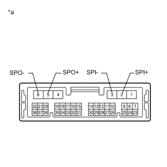
*a Component without harness connected
(Telematics Transceiver)
Measure the resistance according to the value(s) in the table below.
Standard Resistance Tester Connection Condition Specified Condition 2 (SPI+) - 5 (SPO+) Always Below 1 Ω 3 (SPI-) - 6 (SPO-) Always Below 1 Ω 2 (SPI+) - 3 (SPI-) Always 10 kΩ or higher 5 (SPO+) - 6 (SPO-) Always 10 kΩ or higher 2 (SPI+) - Body ground Always 10 kΩ or higher 3 (SPI-) - Body ground Always 10 kΩ or higher Result Proceed to OK NG
OK
GO TO STEP 15 Click here
NG
REPLACE TELEMATICS TRANSCEIVER Click here
-
-
CHECK HARNESS AND CONNECTOR (STEREO COMPONENT AMPLIFIER ASSEMBLY - BODY GROUND)
-
Disconnect the T20 stereo component amplifier assembly connector.
-
Disconnect the O54 and O55 front No. 2 speaker assembly connectors.
-
Disconnect the R14 and S14 front No. 1 speaker assembly connectors.
-
Disconnect the O56 front No. 3 speaker assembly connector.
-
Disconnect the T26 and U36 rear No. 2 speaker assembly connectors.
-
Disconnect the T23 and U34 rear header speaker assembly connectors.
-
Disconnect the T24 rear No. 3 speaker assembly connector.
-
Measure the resistance between the stereo component amplifier assembly and body ground to check for a short circuit in the wire harness.
Standard Resistance Tester Connection Condition Specified Condition T20-13 (FR+) - Body ground Always 10 kΩ or higher T20-28 (FR-) - Body ground Always 10 kΩ or higher T20-12 (FL+) - Body ground Always 10 kΩ or higher T20-27 (FL-) - Body ground Always 10 kΩ or higher T20-5 (WFR+) - Body ground Always 10 kΩ or higher T20-20 (WFR-) - Body ground Always 10 kΩ or higher T20-4 (WFL+) - Body ground Always 10 kΩ or higher T20-19 (WFL-) - Body ground Always 10 kΩ or higher T20-7 (CTR+) - Body ground Always 10 kΩ or higher T20-22 (CTR-) - Body ground Always 10 kΩ or higher T20-15 (RR+) - Body ground Always 10 kΩ or higher T20-30 (RR-) - Body ground Always 10 kΩ or higher T20-14 (RL+) - Body ground Always 10 kΩ or higher T20-29 (RL-) - Body ground Always 10 kΩ or higher T20-11 (SR+) - Body ground Always 10 kΩ or higher T20-26 (SR-) - Body ground Always 10 kΩ or higher T20-10 (SL+) - Body ground Always 10 kΩ or higher T20-25 (SL-) - Body ground Always 10 kΩ or higher T20-6 (WF1+) - Body ground Always 10 kΩ or higher T20-21 (WF1-) - Body ground Always 10 kΩ or higher Result Proceed to OK NG
NG
REPAIR OR REPLACE HARNESS OR CONNECTOR
OK
-
-
CHECK HARNESS AND CONNECTOR (REAR NO. 2 SPEAKER ASSEMBLY - BODY GROUND)
-
Disconnect the T25 and U35 rear speaker assembly connectors.
-
Disconnect the T26 and U36 rear No. 2 speaker assembly connectors.
-
Measure the resistance between each of the rear No. 2 speaker assemblies and body ground to check for a short circuit in the wire harness.
Standard Resistance Tester Connection Condition Specified Condition T26-4 (+) - Body ground Always 10 kΩ or higher T26-2 (-) - Body ground Always 10 kΩ or higher U36-4 (+) - Body ground Always 10 kΩ or higher U36-2 (-) - Body ground Always 10 kΩ or higher Result Proceed to OK NG
NG
REPAIR OR REPLACE HARNESS OR CONNECTOR
OK
-
-
INSPECT FRONT NO. 2 SPEAKER ASSEMBLY
-
Remove the front No. 2 speaker assembly.
-
*a Component without harness connected
(Front No. 2 Speaker Assembly)
Measure the resistance according to the value(s) in the table below.
Standard Resistance Tester Connection Condition Specified Condition 1 (-) - 2 (+) Always 6.5 to 9.7 Ω Result Proceed to OK NG
NG
REPLACE FRONT NO. 2 SPEAKER ASSEMBLY Click here
OK
-
-
REPLACE FRONT NO. 2 SPEAKER ASSEMBLY
-
Replace the front No. 2 speaker assembly with a new or known good one.
-
Clear the DTCs.
Body Electrical > Navigation System > Clear DTCs -
Recheck for DTCs and check that no DTCs are output.
Body Electrical > Navigation System > Trouble CodesOK No DTCs are output. Tech Tips
-
Connect all the connectors to the front No. 2 speaker assemblies that were disconnected.
-
When there is a possibility that either the right or left front No. 2 speaker assembly is defective, inspect by interchanging the right one with the left one.
-
Perform the above inspection on both the LH and RH side.
Result Proceed to OK NG -
OK
END
NG
-
-
INSPECT FRONT NO. 1 SPEAKER ASSEMBLY
-
Remove the front No. 1 speaker assembly.
-
*a Component without harness connected
(Front No. 1 Speaker Assembly)
Measure the resistance according to the value(s) in the table below.
Standard Resistance Tester Connection Condition Specified Condition 1 - 2 Always 4.3 to 6.3 Ω Result Proceed to OK NG
NG
REPLACE FRONT NO. 1 SPEAKER ASSEMBLY Click here
OK
-
-
INSPECT FRONT NO. 3 SPEAKER ASSEMBLY
-
Remove the front No. 3 speaker assembly.
-
*a Component without harness connected
(Front No. 3 Speaker Assembly)
Measure the resistance according to the value(s) in the table below.
Standard Resistance Tester Connection Condition Specified Condition 1 (-) - 2 (+) Always 6.5 to 9.7 Ω Result Proceed to OK NG
NG
REPLACE FRONT NO. 3 SPEAKER ASSEMBLY Click here
OK
-
-
REPLACE FRONT NO. 3 SPEAKER ASSEMBLY
-
Replace the front No. 3 speaker assembly with a new or known good one.
-
Clear the DTCs.
Body Electrical > Navigation System > Clear DTCs -
Recheck for DTCs and check that no DTCs are output.
Body Electrical > Navigation System > Trouble CodesOK No DTCs are output. Result Proceed to OK NG
OK
END
NG
-
-
INSPECT REAR SPEAKER ASSEMBLY
-
Remove the rear speaker assembly.
-
*a Component without harness connected
(Rear Speaker Assembly)
Measure the resistance according to the value(s) in the table below.
Standard Resistance Tester Connection Condition Specified Condition 1 - 2 Always 3.6 to 5.6 Ω Result Proceed to OK NG
NG
REPLACE REAR SPEAKER ASSEMBLY Click here
OK
-
-
INSPECT REAR NO. 2 SPEAKER ASSEMBLY
-
Remove the rear No. 2 speaker assembly.
-
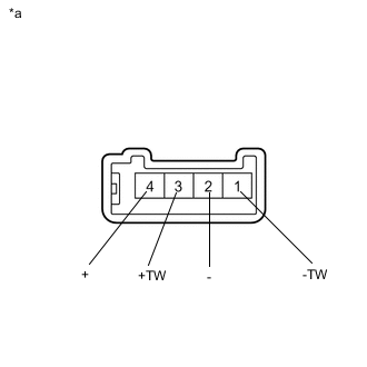
*a Component without harness connected
(Rear No. 2 Speaker Assembly)
Measure the resistance according to the value(s) in the table below.
Standard Resistance Tester Connection Condition Specified Condition 3 (+TW) - 1 (-TW) Always 10 kΩ or higher 3 (+TW) - 4 (+) Always Below 1 Ω 1 (-TW) - 2 (-) Always Below 1 Ω Result Proceed to OK NG
NG
REPLACE REAR NO. 2 SPEAKER ASSEMBLY Click here
OK
-
-
REPLACE REAR NO. 2 SPEAKER ASSEMBLY
-
Replace the rear No. 2 speaker assembly with a new or known good one.
-
Clear the DTCs.
Body Electrical > Navigation System > Clear DTCs -
Recheck for DTCs and check that no DTCs are output.
Body Electrical > Navigation System > Trouble CodesOK No DTCs are output. Tech Tips
-
Connect all the connectors to the rear No. 2 speaker assemblies that were disconnected.
-
When there is a possibility that either the right or left rear No. 2 speaker assembly is defective, inspect by interchanging the right one with the left one.
-
Perform the above inspection on both the LH and RH side.
Result Proceed to OK NG -
OK
END
NG
-
-
INSPECT REAR HEADER SPEAKER ASSEMBLY
-
Remove the rear header speaker assembly.
-
*a Component without harness connected
(Rear Header Speaker Assembly)
Measure the resistance according to the value(s) in the table below.
Standard Resistance Tester Connection Condition Specified Condition 1 - 2 Always 6.5 to 9.7 Ω Result Proceed to OK NG
NG
REPLACE REAR HEADER SPEAKER ASSEMBLY Click here
OK
-
-
REPLACE REAR HEADER SPEAKER ASSEMBLY
-
Replace the rear header speaker assembly with a new or known good one.
-
Clear the DTCs.
Body Electrical > Navigation System > Clear DTCs -
Recheck for DTCs and check that no DTCs are output.
Body Electrical > Navigation System > Trouble CodesOK No DTCs are output. Tech Tips
-
Connect all the connectors to the rear header speaker assemblies that were disconnected.
-
When there is a possibility that either the right or left rear header speaker assembly is defective, inspect by interchanging the right one with the left one.
-
Perform the above inspection on both the LH and RH side.
Result Proceed to OK NG -
OK
END
NG
-
-
INSPECT REAR NO. 3 SPEAKER ASSEMBLY
-
Remove the rear No. 3 speaker assembly.
-
*a Component without harness connected
(Rear No. 3 Speaker Assembly)
Measure the resistance according to the value(s) in the table below.
Standard Resistance Tester Connection Condition Specified Condition 1 - 2 Always 4.8 to 6.8 Ω Result Proceed to OK NG
OK
REPLACE STEREO COMPONENT AMPLIFIER ASSEMBLY Click here
NG
REPLACE REAR NO. 3 SPEAKER ASSEMBLY Click here
-