| DTC Code | DTC Name |
|---|---|
| AVC-LAN Circuit |
DESCRIPTION
Each unit of the audio and visual system connected to the AVC-LAN (communication bus) transfers switch signals through the AVC-LAN.
If a short to +B or short to ground occurs in the AVC-LAN, the audio and visual system will not function normally because communication is not possible.
PROCEDURE
- Click here
INSPECT RADIO RECEIVER ASSEMBLY
-
Remove the radio receiver assembly.
-
*a Component without harness connected
(Radio Receiver Assembly)
*a Component without harness connected
(Radio Receiver Assembly)
*a Component without harness connected
(Radio Receiver Assembly)
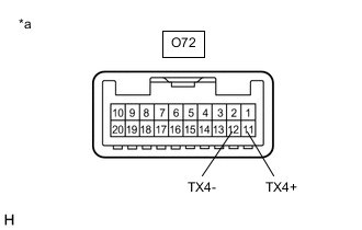
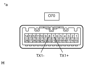
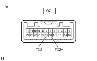
Measure the resistance according to the value(s) in the table below.
Standard Resistance Tester Connection Condition Specified Condition O71-18 (TX2+) - O71-19 (TX2-) Always 60 to 80 Ω O70-7 (TX1+) - O70-8 (TX1-) Always 60 to 80 Ω O72-11 (TX4+) - O72-12 (TX4-) Always 60 to 80 Ω Result Proceed to OK NG
- OKClick here
- NG
REPLACE RADIO RECEIVER ASSEMBLYClick here
-
- Click here
CHECK HARNESS AND CONNECTOR (AVC-LAN CIRCUIT)
-
Disconnect the O70, O71 and O72 radio receiver assembly connectors.
-
Disconnect the T21 stereo component amplifier assembly connector.
-
Disconnect the O60 multi-display assembly connector.
-
Disconnect the O76 remote operation controller assembly connector.
-
Measure the resistance according to the value(s) in the table below.
Standard Resistance Tester Connection Condition Specified Condition O70-7 (TX1+) - T21-8 (TX+) Always Below 1 Ω O70-8 (TX1-) - T21-7 (TX-) Always Below 1 Ω O72-11 (TX4+) - O60-7 (TX+) Always Below 1 Ω O72-12 (TX4-) - O60-19 (TX-) Always Below 1 Ω O71-18 (TX2+) - O76-10 (TX+) Always Below 1 Ω O71-19 (TX2-) - O76-11 (TX-) Always Below 1 Ω O70-7 (TX1+) - Body ground Always 10 kΩ or higher O70-8 (TX1-) - Body ground Always 10 kΩ or higher O72-11 (TX4+) - Body ground Always 10 kΩ or higher O72-12 (TX4-) - Body ground Always 10 kΩ or higher O71-18 (TX2+) - Body ground Always 10 kΩ or higher O71-19 (TX2-) - Body ground Always 10 kΩ or higher Result Proceed to OK NG
- OKClick here
- NG
REPAIR OR REPLACE HARNESS OR CONNECTOR
-
- Click here
INSPECT MALFUNCTIONING PARTS
-
Disconnect and reconnect each slave unit one by one until the master unit returns to normal operation.
Tip:
-
Check all slave units.
-
If disconnecting a slave unit causes the master unit to return to normal operation, the slave unit is defective and should be replaced.
OK Master unit returns to normal operation. Result Proceed to OK NG -
- OK
REPLACE MALFUNCTIONING PARTS
- NG
REPLACE RADIO RECEIVER ASSEMBLYClick here
-