| DTC Code | DTC Name |
|---|---|
| Switch Operation of Remote Touch not Accepted |
CAUTION / NOTICE / HINT
-
Depending on the parts that are replaced during vehicle inspection or maintenance, performing initialization, registration or calibration may be needed. Refer to Precaution for Audio and Visual System.
-
When replacing the radio receiver assembly, always replace it with a new one. If a radio receiver assembly which was installed to another vehicle is used, the following may occur:
-
-
A communication malfunction DTC may be stored.
-
The radio receiver assembly may not operate normally.
-
PROCEDURE
- Click here
START DIAGNOSTIC MODE
-
Enter diagnostic mode and check if the "Service Menu" screen can be displayed.
OK Diagnostic mode can be activated. Result Proceed to OK NG
- OKClick here
- NGClick here
-
- Click here
CHECK PANEL SWITCH (OPERATION CHECK)
-
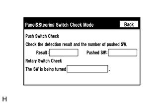
Enter the "Panel & Steering Switch Check Mode" screen. Refer to Check Panel & Steering Switch in Operation Check.
-
Operate the abnormal switch and check if the switch status is correctly displayed.
OK The switch status is correctly displayed as operated. Result Proceed to OK NG
- OK
REPLACE RADIO RECEIVER ASSEMBLYClick here
- NGClick here
GO TO STEP 3
-
- Click here
REMOTE TOUCH (REMOTE OPERATION CONTROLLER ASSEMBLY) SELF CHECK (SWITCH OPERATION CHECK)
-
Activate self-diagnostic mode.
-
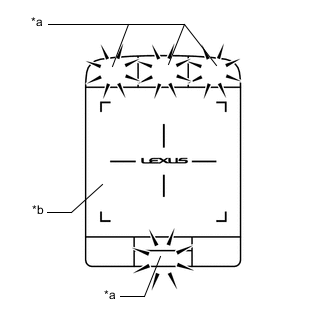
*a Switch Illumination *b Remote Touch Screen Operate the remote touch screen in the upper left to turn the switch illumination off.
Note:Since the remote touch screen may recognize a pinch in/out or flick operation if operated with 2 fingers, always use 1 finger to operate the remote touch (remote operation controller assembly) in self-diagnostic mode.
-
With the switch illumination turned off, press each switch of the remote touch (remote operation controller assembly) and check that the switch illumination turns on.
Result Result Proceed to Self-diagnostic mode cannot be activated. A Some switches do not turn on the switch illumination when they are pressed. All switches turn on the switch illumination when they are pressed. B
- A
REPLACE REMOTE TOUCH (REMOTE OPERATION CONTROLLER ASSEMBLY)Click here
- B
REPLACE RADIO RECEIVER ASSEMBLYClick here
-