| DTC Code | DTC Name |
|---|---|
| B1323 | Lost Communication with Haptic Device |
| B1324 | Lost Communication with Meter |
DESCRIPTION
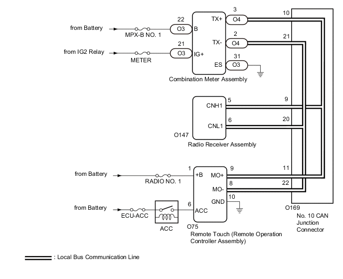
These DTCs are stored when communication between the radio receiver assembly and remote touch (remote operation controller assembly) or combination meter assembly is not possible.
| DTC No. | Detection Item | DTC Detection Condition | Trouble Area |
|---|---|---|---|
| B1323 | Lost Communication with Haptic Device | CAN reception error |
|
| B1324 | Lost Communication with Meter | CAN reception error |
|
The radio receiver assembly is the master unit.

CAUTION / NOTICE / HINT
-
Depending on the parts that are replaced during vehicle inspection or maintenance, performing initialization, registration or calibration may be needed. Refer to Precaution for Audio and Visual System.
-
When replacing the radio receiver assembly, always replace it with a new one. If a radio receiver assembly which was installed to another vehicle is used, the following may occur:
-
-
A communication malfunction DTC may be stored.
-
The radio receiver assembly may not operate normally.
-
-
Inspect the fuses for circuits related to this system before performing the following inspection procedure.
PROCEDURE
- Click here
CHECK MODEL
-
Choose the model to be inspected.
Result Result Proceed to for LHD A for RHD B
-
- Click here
CHECK DTC
-
Clear the DTCs.
- Body Electrical > Navigation System > Clear DTCs
-
-
-
Recheck for DTCs and check that no DTCs are output.
- Body Electrical > Navigation System > Trouble Codes
-
-
Result Result Proceed to All DTCs are not output A DTCs B1323 and B1324 are output B DTC B1323 is output C DTC B1324 is output D
- A
USE SIMULATION METHOD TO CHECKClick here
- BClick here
- CClick here
- DClick here
-
- Click here
CHECK LOCAL BUS
-
Disconnect the cable from the negative (-) battery terminal.
-
Measure the resistance according to the value(s) in the table below.
Standard Resistance Tester Connection Condition Specified Condition O169-9 - O169-20 Cable disconnected from negative (-) battery terminal 54 to 69 Ω Result Result Proceed to OK A NG (Below 54 Ω) B NG (70 Ω or higher) C
- A
USE SIMULATION METHOD TO CHECKClick here
- BClick here
- CClick here
-
- Click here
CHECK HARNESS AND CONNECTOR (RADIO RECEIVER ASSEMBLY - NO. 10 CAN JUNCTION CONNECTOR)
-
Disconnect the cable from the negative (-) battery terminal.
-
Disconnect the O169 No. 10 CAN junction connector.
-
Connect the O147 radio receiver assembly connector.
-
Measure the resistance according to the value(s) in the table below.
Standard Resistance Tester Connection Condition Specified Condition O169-9 - O169-20 Cable disconnected from negative (-) battery terminal 108 to 132 Ω Result Proceed to OK NG
- OKClick here
- NGClick here
-
- Click here
CHECK HARNESS AND CONNECTOR (COMBINATION METER ASSEMBLY - NO. 10 CAN JUNCTION CONNECTOR)
-
Disconnect the cable from the negative (-) battery terminal.
-
Disconnect the O169 No. 10 CAN junction connector.
-
Connect the O4 combination meter assembly connector.
-
Measure the resistance according to the value(s) in the table below.
Standard Resistance Tester Connection Condition Specified Condition O169-10 - O169-21 Cable disconnected from negative (-) battery terminal 200 Ω or higher Result Proceed to OK NG
- OKClick here
- NGClick here
-
- Click here
CHECK HARNESS AND CONNECTOR (REMOTE TOUCH (REMOTE OPERATION CONTROLLER ASSEMBLY) - NO. 10 CAN JUNCTION CONNECTOR)
-
Disconnect the cable from the negative (-) battery terminal.
-
Disconnect the O169 No. 10 CAN junction connector.
-
Connect the O75 remote touch (remote operation controller assembly) connector.
-
Measure the resistance according to the value(s) in the table below.
Standard Resistance Tester Connection Condition Specified Condition O169-11 - O169-22 Cable disconnected from negative (-) battery terminal 108 to 132 Ω Result Proceed to OK NG
- OK
REPLACE NO. 10 CAN JUNCTION CONNECTOR
- NGClick here
-
- Click here
CHECK HARNESS AND CONNECTOR (REMOTE TOUCH (REMOTE OPERATION CONTROLLER ASSEMBLY) - NO. 10 CAN JUNCTION CONNECTOR)
-
Disconnect the cable from the negative (-) battery terminal.
-
Disconnect the O75 remote touch (remote operation controller assembly) connector.
-
Connect the O169 No. 10 CAN junction connector.
-
Measure the resistance according to the value(s) in the table below.
Standard Resistance Tester Connection Condition Specified Condition O75-9 (MO+) - O75-8 (MO-) Cable disconnected from negative (-) battery terminal 108 to 132 Ω Result Proceed to OK NG
- OK
REPLACE REMOTE TOUCH (REMOTE OPERATION CONTROLLER ASSEMBLY)Click here
- NG
REPAIR OR REPLACE HARNESS OR CONNECTOR
-
- Click here
CHECK HARNESS AND CONNECTOR (COMBINATION METER ASSEMBLY - NO. 10 CAN JUNCTION CONNECTOR)
-
Disconnect the cable from the negative (-) battery terminal.
-
Disconnect the O4 combination meter assembly connector.
-
Connect the O169 No. 10 CAN junction connector.
-
Measure the resistance according to the value(s) in the table below.
Standard Resistance Tester Connection Condition Specified Condition O4-3 (TX+) - O4-2 (TX-) Cable disconnected from negative (-) battery terminal 54 to 69 Ω Result Proceed to OK NG
- OK
REPLACE COMBINATION METER ASSEMBLYClick here
- NG
REPAIR OR REPLACE HARNESS OR CONNECTOR
-
- Click here
CHECK HARNESS AND CONNECTOR (RADIO RECEIVER ASSEMBLY - NO. 10 CAN JUNCTION CONNECTOR)
-
Disconnect the cable from the negative (-) battery terminal.
-
Disconnect the O147 radio receiver assembly connector.
-
Connect the O169 No. 10 CAN junction connector.
-
Measure the resistance according to the value(s) in the table below.
Standard Resistance Tester Connection Condition Specified Condition O147-5 (CNH1) - O147-6 (CNL1) Cable disconnected from negative (-) battery terminal 108 to 132 Ω Result Proceed to OK NG
- OK
REPLACE RADIO RECEIVER ASSEMBLYClick here
- NGClick here
-
- Click here
CHECK HARNESS AND CONNECTOR (RADIO RECEIVER ASSEMBLY - NO. 10 CAN JUNCTION CONNECTOR)
-
Disconnect the cable from the negative (-) battery terminal.
-
Disconnect the O169 No. 10 CAN junction connector.
-
Connect the O147 radio receiver assembly connector.
-
Measure the resistance according to the value(s) in the table below.
Standard Resistance Tester Connection Condition Specified Condition O169-9 - O169-20 Cable disconnected from negative (-) battery terminal 108 to 132 Ω Result Proceed to OK NG
- OK
REPLACE NO. 10 CAN JUNCTION CONNECTOR
- NG
REPAIR OR REPLACE HARNESS OR CONNECTOR
-
- Click here
CHECK HARNESS AND CONNECTOR (REMOTE TOUCH (REMOTE OPERATION CONTROLLER ASSEMBLY) POWER SOURCE)
-
Disconnect the O75 remote touch (remote operation controller assembly) connector.
-
Measure the resistance according to the value(s) in the table below.
Standard Resistance Tester Connection Condition Specified Condition O75-10 (GND) - Body ground Always Below 1 Ω -
Measure the voltage according to the value(s) in the table below.
Standard Voltage Tester Connection Condition Specified Condition O75-1 (+B) - Body ground Always 11 to 14 V O75-6 (ACC) - Body ground Engine switch on (IG) 11 to 14 V Result Proceed to OK NG
- OKClick here
- NG
REPAIR OR REPLACE HARNESS OR CONNECTOR
-
- Click here
CHECK HARNESS AND CONNECTOR (REMOTE TOUCH (REMOTE OPERATION CONTROLLER ASSEMBLY) - NO. 10 CAN JUNCTION CONNECTOR)
-
Disconnect the cable from the negative (-) battery terminal.
-
Disconnect the O169 No. 10 CAN junction connector.
-
Connect the O75 remote touch (remote operation controller assembly) connector.
-
Measure the resistance according to the value(s) in the table below.
Standard Resistance Tester Connection Condition Specified Condition O169-11 - O169-22 Cable disconnected from negative (-) battery terminal 108 to 132 Ω Result Proceed to OK NG
- OK
REPLACE NO. 10 CAN JUNCTION CONNECTOR
- NGClick here
-
- Click here
CHECK HARNESS AND CONNECTOR (REMOTE TOUCH (REMOTE OPERATION CONTROLLER ASSEMBLY) - NO. 10 CAN JUNCTION CONNECTOR)
-
Disconnect the cable from the negative (-) battery terminal.
-
Disconnect the O75 remote touch (remote operation controller assembly) connector.
-
Connect the O169 No. 10 CAN junction connector.
-
Measure the resistance according to the value(s) in the table below.
Standard Resistance Tester Connection Condition Specified Condition O75-9 (MO+) - O75-8 (MO-) Cable disconnected from negative (-) battery terminal 108 to 132 Ω Result Proceed to OK NG
- OK
REPLACE REMOTE TOUCH (REMOTE OPERATION CONTROLLER ASSEMBLY)Click here
- NG
REPAIR OR REPLACE HARNESS OR CONNECTOR
-
- Click here
CHECK HARNESS AND CONNECTOR (COMBINATION METER ASSEMBLY POWER SOURCE)
-
Disconnect the O3 combination meter assembly connector.
-
Measure the resistance according to the value(s) in the table below.
Standard Resistance Tester Connection Condition Specified Condition O3-31 (ES) - Body ground Always Below 1 Ω -
Measure the voltage according to the value(s) in the table below.
Standard Voltage Tester Connection Condition Specified Condition O3-22 (B) - Body ground Always 11 to 14 V O3-21 (IG+) - Body ground Engine switch on (IG) 11 to 14 V Result Proceed to OK NG
- OKClick here
- NG
REPAIR OR REPLACE HARNESS OR CONNECTOR
-
- Click here
CHECK HARNESS AND CONNECTOR (COMBINATION METER ASSEMBLY - NO. 10 CAN JUNCTION CONNECTOR)
-
Disconnect the cable from the negative (-) battery terminal.
-
Disconnect the O169 No. 10 CAN junction connector.
-
Connect the O4 combination meter assembly connector.
-
Measure the resistance according to the value(s) in the table below.
Standard Resistance Tester Connection Condition Specified Condition O169-10 - O169-21 Cable disconnected from negative (-) battery terminal 200 Ω or higher Result Proceed to OK NG
- OK
REPLACE NO. 10 CAN JUNCTION CONNECTOR
- NGClick here
-
- Click here
CHECK HARNESS AND CONNECTOR (COMBINATION METER ASSEMBLY - NO. 10 CAN JUNCTION CONNECTOR)
-
Disconnect the cable from the negative (-) battery terminal.
-
Disconnect the O4 combination meter assembly connector.
-
Connect the O169 No. 10 CAN junction connector.
-
Measure the resistance according to the value(s) in the table below.
Standard Resistance Tester Connection Condition Specified Condition O4-3 (TX+) - O4-2 (TX-) Cable disconnected from negative (-) battery terminal 54 to 69 Ω Result Proceed to OK NG
- OK
REPLACE COMBINATION METER ASSEMBLYClick here
- NG
REPAIR OR REPLACE HARNESS OR CONNECTOR
-
- Click here
CHECK DTC
-
Clear the DTCs.
- Body Electrical > Navigation System > Clear DTCs
-
-
-
Recheck for DTCs and check that no DTCs are output.
- Body Electrical > Navigation System > Trouble Codes
-
-
Result Result Proceed to All DTCs are not output A DTCs B1323 and B1324 are output B DTC B1323 is output C DTC B1324 is output D
- A
USE SIMULATION METHOD TO CHECKClick here
- BClick here
- CClick here
- DClick here
-
- Click here
CHECK LOCAL BUS
-
Disconnect the cable from the negative (-) battery terminal.
-
Measure the resistance according to the value(s) in the table below.
Standard Resistance Tester Connection Condition Specified Condition O110-9 - O110-20 Cable disconnected from negative (-) battery terminal 54 to 69 Ω Result Result Proceed to OK A NG (Below 54 Ω) B NG (70 Ω or higher) C
- A
USE SIMULATION METHOD TO CHECKClick here
- BClick here
- CClick here
-
- Click here
CHECK HARNESS AND CONNECTOR (RADIO RECEIVER ASSEMBLY - NO. 6 CAN JUNCTION CONNECTOR)
-
Disconnect the cable from the negative (-) battery terminal.
-
Disconnect the O110 No. 6 CAN junction connector.
-
Connect the O147 radio receiver assembly connector.
-
Measure the resistance according to the value(s) in the table below.
Standard Resistance Tester Connection Condition Specified Condition O110-9 - O110-20 Cable disconnected from negative (-) battery terminal 108 to 132 Ω Result Proceed to OK NG
- OKClick here
- NGClick here
-
- Click here
CHECK HARNESS AND CONNECTOR (COMBINATION METER ASSEMBLY - NO. 6 CAN JUNCTION CONNECTOR)
-
Disconnect the cable from the negative (-) battery terminal.
-
Disconnect the O110 No. 6 CAN junction connector.
-
Connect the O4 combination meter assembly connector.
-
Measure the resistance according to the value(s) in the table below.
Standard Resistance Tester Connection Condition Specified Condition O110-10 - O110-21 Cable disconnected from negative (-) battery terminal 200 Ω or higher Result Proceed to OK NG
- OKClick here
- NGClick here
-
- Click here
CHECK HARNESS AND CONNECTOR (REMOTE TOUCH (REMOTE OPERATION CONTROLLER ASSEMBLY) - NO. 6 CAN JUNCTION CONNECTOR)
-
Disconnect the cable from the negative (-) battery terminal.
-
Disconnect the O110 No. 6 CAN junction connector.
-
Connect the O75 remote touch (remote operation controller assembly) connector.
-
Measure the resistance according to the value(s) in the table below.
Standard Resistance Tester Connection Condition Specified Condition O110-11 - O110-22 Cable disconnected from negative (-) battery terminal 108 to 132 Ω Result Proceed to OK NG
- OK
REPLACE NO. 6 CAN JUNCTION CONNECTOR
- NGClick here
-
- Click here
CHECK HARNESS AND CONNECTOR (REMOTE TOUCH (REMOTE OPERATION CONTROLLER ASSEMBLY) - NO. 6 CAN JUNCTION CONNECTOR)
-
Disconnect the cable from the negative (-) battery terminal.
-
Disconnect the O75 remote touch (remote operation controller assembly) connector.
-
Connect the O110 No. 6 CAN junction connector.
-
Measure the resistance according to the value(s) in the table below.
Standard Resistance Tester Connection Condition Specified Condition O75-9 (MO+) - O75-8 (MO-) Cable disconnected from negative (-) battery terminal 108 to 132 Ω Result Proceed to OK NG
- OK
REPLACE REMOTE TOUCH (REMOTE OPERATION CONTROLLER ASSEMBLY)Click here
- NG
REPAIR OR REPLACE HARNESS OR CONNECTOR
-
- Click here
CHECK HARNESS AND CONNECTOR (COMBINATION METER ASSEMBLY - NO. 6 CAN JUNCTION CONNECTOR)
-
Disconnect the cable from the negative (-) battery terminal.
-
Disconnect the O4 combination meter assembly connector.
-
Connect the O110 No. 6 CAN junction connector.
-
Measure the resistance according to the value(s) in the table below.
Standard Resistance Tester Connection Condition Specified Condition O4-3 (TX+) - O4-2 (TX-) Cable disconnected from negative (-) battery terminal 54 to 69 Ω Result Proceed to OK NG
- OK
REPLACE COMBINATION METER ASSEMBLYClick here
- NG
REPAIR OR REPLACE HARNESS OR CONNECTOR
-
- Click here
CHECK HARNESS AND CONNECTOR (RADIO RECEIVER ASSEMBLY - NO. 6 CAN JUNCTION CONNECTOR)
-
Disconnect the cable from the negative (-) battery terminal.
-
Disconnect the O147 radio receiver assembly connector.
-
Connect the O110 No. 6 CAN junction connector.
-
Measure the resistance according to the value(s) in the table below.
Standard Resistance Tester Connection Condition Specified Condition O147-5 (CNH1) - O147-6 (CNL1) Cable disconnected from negative (-) battery terminal 108 to 132 Ω Result Proceed to OK NG
- OK
REPLACE RADIO RECEIVER ASSEMBLYClick here
- NG
REPAIR OR REPLACE HARNESS OR CONNECTOR
-
- Click here
CHECK HARNESS AND CONNECTOR (RADIO RECEIVER ASSEMBLY - NO. 6 CAN JUNCTION CONNECTOR)
-
Disconnect the cable from the negative (-) battery terminal.
-
Disconnect the O159 radio receiver assembly connector.
-
Connect the O110 No. 6 CAN junction connector.
-
Measure the resistance according to the value(s) in the table below.
Standard Resistance Tester Connection Condition Specified Condition O147-5 (CNH1) - O147-6 (CNL1) Cable disconnected from negative (-) battery terminal 108 to 132 Ω Result Proceed to OK NG
- OK
REPLACE RADIO RECEIVER ASSEMBLYClick here
- NGClick here
-
- Click here
CHECK HARNESS AND CONNECTOR (RADIO RECEIVER ASSEMBLY - NO. 6 CAN JUNCTION CONNECTOR)
-
Disconnect the cable from the negative (-) battery terminal.
-
Disconnect the O110 No. 6 CAN junction connector.
-
Connect the O147 radio receiver assembly connector.
-
Measure the resistance according to the value(s) in the table below.
Standard Resistance Tester Connection Condition Specified Condition O110-9 - O110-20 Cable disconnected from negative (-) battery terminal 108 to 132 Ω Result Proceed to OK NG
- OK
REPLACE NO. 6 CAN JUNCTION CONNECTOR
- NG
REPAIR OR REPLACE HARNESS OR CONNECTOR
-
- Click here
CHECK HARNESS AND CONNECTOR (REMOTE TOUCH (REMOTE OPERATION CONTROLLER ASSEMBLY) POWER SOURCE)
-
Disconnect the O75 remote touch (remote operation controller assembly) connector.
-
Measure the resistance according to the value(s) in the table below.
Standard Resistance Tester Connection Condition Specified Condition O75-10 (GND) - Body ground Always Below 1 Ω -
Measure the voltage according to the value(s) in the table below.
Standard Voltage Tester Connection Condition Specified Condition O75-1 (+B) - Body ground Always 11 to 14 V O75-6 (ACC) - Body ground Engine switch on (IG) 11 to 14 V Result Proceed to OK NG
- OKClick here
- NG
REPAIR OR REPLACE HARNESS OR CONNECTOR
-
- Click here
CHECK HARNESS AND CONNECTOR (REMOTE TOUCH (REMOTE OPERATION CONTROLLER ASSEMBLY) - NO. 6 CAN JUNCTION CONNECTOR)
-
Disconnect the cable from the negative (-) battery terminal.
-
Disconnect the O110 No. 6 CAN junction connector.
-
Connect the O75 remote touch (remote operation controller assembly) connector.
-
Measure the resistance according to the value(s) in the table below.
Standard Resistance Tester Connection Condition Specified Condition O110-11 - O110-22 Cable disconnected from negative (-) battery terminal 108 to 132 Ω Result Proceed to OK NG
- OK
REPLACE NO. 6 CAN JUNCTION CONNECTOR
- NGClick here
-
- Click here
CHECK HARNESS AND CONNECTOR (REMOTE TOUCH (REMOTE OPERATION CONTROLLER ASSEMBLY) - NO. 6 CAN JUNCTION CONNECTOR)
-
Disconnect the cable from the negative (-) battery terminal.
-
Disconnect the O75 remote touch (remote operation controller assembly) connector.
-
Connect the O110 No. 6 CAN junction connector.
-
Measure the resistance according to the value(s) in the table below.
Standard Resistance Tester Connection Condition Specified Condition O75-9 (MO+) - O75-8 (MO-) Cable disconnected from negative (-) battery terminal 108 to 132 Ω Result Proceed to OK NG
- OK
REPLACE REMOTE TOUCH (REMOTE OPERATION CONTROLLER ASSEMBLY)Click here
- NG
REPAIR OR REPLACE HARNESS OR CONNECTOR
-
- Click here
CHECK HARNESS AND CONNECTOR (COMBINATION METER ASSEMBLY POWER SOURCE)
-
Disconnect the O3 combination meter assembly connector.
-
Measure the resistance according to the value(s) in the table below.
Standard Resistance Tester Connection Condition Specified Condition O3-31 (ES) - Body ground Always Below 1 Ω -
Measure the voltage according to the value(s) in the table below.
Standard Voltage Tester Connection Condition Specified Condition O3-22 (B) - Body ground Always 11 to 14 V O3-21 (IG+) - Body ground Engine switch on (IG) 11 to 14 V Result Proceed to OK NG
- OKClick here
- NG
REPAIR OR REPLACE HARNESS OR CONNECTOR
-
- Click here
CHECK HARNESS AND CONNECTOR (COMBINATION METER ASSEMBLY - NO. 6 CAN JUNCTION CONNECTOR)
-
Disconnect the cable from the negative (-) battery terminal.
-
Disconnect the O110 No. 6 CAN junction connector.
-
Connect the O4 combination meter assembly connector.
-
Measure the resistance according to the value(s) in the table below.
Standard Resistance Tester Connection Condition Specified Condition O110-10 - O110-21 Cable disconnected from negative (-) battery terminal 200 Ω or higher Result Proceed to OK NG
- OK
REPLACE NO. 6 CAN JUNCTION CONNECTOR
- NGClick here
-
- Click here
CHECK HARNESS AND CONNECTOR (COMBINATION METER ASSEMBLY - NO. 6 CAN JUNCTION CONNECTOR)
-
Disconnect the cable from the negative (-) battery terminal.
-
Disconnect the O4 combination meter assembly connector.
-
Connect the O110 No. 6 CAN junction connector.
-
Measure the resistance according to the value(s) in the table below.
Standard Resistance Tester Connection Condition Specified Condition O4-3 (TX+) - O4-2 (TX-) Cable disconnected from negative (-) battery terminal 54 to 69 Ω Result Proceed to OK NG
- OK
REPLACE COMBINATION METER ASSEMBLYClick here
- NG
REPAIR OR REPLACE HARNESS OR CONNECTOR
-