| DTC Code | DTC Name |
|---|---|
| B15D0 | MOST Communication Malfunction |
DESCRIPTION
This DTC is stored when the MOST network cannot be established after the master unit is activated.
| DTC No. | Detection Item | DTC Detection Condition | Trouble Area |
|---|---|---|---|
| B15D0 | MOST Communication Malfunction | MOST network cannot be established. |
|
-
For the MOST network, the radio receiver assembly is the master unit.
-
Errors may occur in MOST communication between devices due to problems such as electrical noise.
WIRING DIAGRAM
CAUTION / NOTICE / HINT
-
Depending on the parts that are replaced during vehicle inspection or maintenance, performing initialization, registration or calibration may be needed. Refer to Precaution for Audio and Visual System.
-
When replacing the radio receiver assembly, always replace it with a new one. If a radio receiver assembly which was installed to another vehicle is used, the following may occur:
-
-
A communication malfunction DTC may be stored.
-
The radio receiver assembly may not operate normally.
-
PROCEDURE
- Click here
CHECK RESULT OF SYSTEM CHECK MODE
-
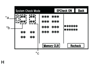
*a Node position number for devices connected to the MOST network *b Device Name *c Result Enter the "System Check Mode" screen. Refer to Check DTC (Check Using System Check Mode Screen) in DTC Check / Clear.
-
Check the result on the "System Check Mode" screen.
Result Result Proceed to "MOST" is displayed for "DCU". A "DETAIL" is displayed for "DCU". B
- AClick here
- B
USE SIMULATION METHOD TO CHECKClick here
-
- Click here
PERFORM MOST LINE CHECK
-
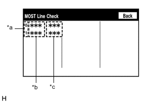
*a Node position number for devices connected to the MOST network *b Device Name *c Result Enter the "MOST Line Check" screen. Refer to Check DTC (Check Using System Check Mode Screen) in DTC Check / Clear.
-
Check if the MOST communication lines connectors and terminals of the radio receiver assembly, stereo component amplifier assembly for connection problems.
-
Check the result on the "MOST Line Check" screen.
Result Result Proceed to "OK" is displayed for all items. A "NCON" is displayed for "AMP". B "NCON" is displayed for "DCU". C Tip:
-
When "NCON" is displayed for more than 1 item, proceed to the step for the device that has the smallest node position number.
-
The "MOST Line Check" screen can be displayed only when DTC B15D0 is stored.
-
- AClick here
- BClick here
- C
REPLACE RADIO RECEIVER ASSEMBLYClick here
-
- Click here
CHECK HARNESS AND CONNECTOR (RADIO RECEIVER ASSEMBLY - STEREO COMPONENT AMPLIFIER ASSEMBLY)
-
Disconnect the j1 radio receiver assembly connector.
-
Disconnect the T34 stereo component amplifier assembly connector.
-
Measure the resistance according to the value(s) in the table below.
Standard Resistance Tester Connection Condition Specified Condition j1-2 (MI+) - T34-5 (MO+) Always Below 1 Ω j1-3 (MI-) - T34-6 (MO-) Always Below 1 Ω j1-4 (SLDI) - T34-7 (SLDO) Always Below 1 Ω j1-5 (MO+) - T34-2 (MI+) Always Below 1 Ω j1-6 (MO-) - T34-3 (MI-) Always Below 1 Ω j1-7 (SLDO) - T34-4 (SLDI) Always Below 1 Ω j1-2 (MI+) or T34-5 (MO+) - Body ground Always 10 kΩ or higher j1-3 (MI-) or T34-6 (MO-) - Body ground Always 10 kΩ or higher j1-4 (SLDI) or T34-7 (SLDO) - Body ground Always 10 kΩ or higher j1-5 (MO+) or T34-2 (MI+) - Body ground Always 10 kΩ or higher j1-6 (MO-) or T34-3 (MI-) - Body ground Always 10 kΩ or higher j1-7 (SLDO) or T34-4 (SLDI) - Body ground Always 10 kΩ or higher Result Proceed to OK NG
- OKClick here
- NG
REPAIR OR REPLACE HARNESS OR CONNECTOR
-
- Click here
REPLACE STEREO COMPONENT AMPLIFIER ASSEMBLY
-
Replace the stereo component amplifier assembly with a new or known good one.
-
Clear the DTCs.
- Body Electrical > Navigation System > Clear DTCs
-
-
-
Recheck for DTCs and check that no DTCs are output.
- Body Electrical > Navigation System > Trouble Codes
-
-
OK No DTCs are output. Result Proceed to OK NG
- OK
END
- NG
REPLACE RADIO RECEIVER ASSEMBLYClick here
-
- Click here
CHECK HARNESS AND CONNECTOR (WAKE-UP SIGNAL)
-
Disconnect the T34 stereo component amplifier assembly connector.
-
Measure the voltage according to the value(s) in the table below.
Standard Voltage Tester Connection Condition Specified Condition T34-8 (WUI) - Body ground Engine switch on (ACC) 4.5 V or higher Result Proceed to OK NG
- OK
REPLACE STEREO COMPONENT AMPLIFIER ASSEMBLYClick here
- NGClick here
-
- Click here
CHECK HARNESS AND CONNECTOR (RADIO RECEIVER ASSEMBLY - STEREO COMPONENT AMPLIFIER ASSEMBLY)
-
Disconnect the j1 radio receiver assembly connector.
-
Disconnect the T34 stereo component amplifier assembly connector.
-
Measure the resistance according to the value(s) in the table below.
Standard Resistance Tester Connection Condition Specified Condition j1-1 (WUO) - T34-8 (WUI) Always Below 1 Ω j1-1 (WUO) or T34-8 (WUI) - Body ground Always 10 kΩ or higher Result Proceed to OK NG
- OK
REPLACE RADIO RECEIVER ASSEMBLYClick here
- NG
REPAIR OR REPLACE HARNESS OR CONNECTOR
-