PROCEDURE
- Click here
INSPECT TIE ROD ASSEMBLY LH
-
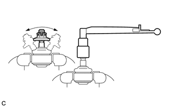
Secure the tie rod assembly LH in a vise between aluminum plates.
Note:Do not overtighten the vise.
-
Install the nut to the stud bolt.
-
Flip the ball joint back and forth 5 times.
-
Using a torque wrench and the nut, turn the stud bolt continuously at a rate of 3 to 5 seconds per turn, and check the turning torque on the 5th turn.
Standard Turning Torque 0.29 to 2.45 N*m (3 to 24 kgf*cm, 3 to 21 in.*lbf) If the turning torque is not within the specified range, replace the tie rod assembly LH with a new one.
-
Check that the ball joint dust cover is not cracked and that there is no grease on it.
If the ball joint dust cover is cracked or there is grease on it, replace the tie rod assembly LH with a new one.
-
- Click here
INSPECT TIE ROD ASSEMBLY RH
Tip:Perform the same procedure as for the LH side.
- Click here
INSPECT TOTAL PRELOAD
Note:Inspect the total preload in a no-load condition by removing the tie rod assembly RH, tie rod assembly LH and steering rack boots.
-
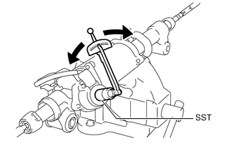
Install SST to the pinion shaft and turn it left and right 5 times or more.
09616-00011 -
Using SST and a torque wrench, turn the pinion shaft continuously at a rate of 4 to 6 seconds per turn to check the total preload of the power steering link assembly.
Standard Preload 1.5 to 2.46 N*m (16 to 25 kgf*cm, 14 to 21 in.*lbf) Note:Check the total preload around the steering rack center position.
If the total preload is not within the specified range, replace the power steering link assembly with a new one.
-
- Click here
INSPECT POWER STEERING LINK ASSEMBLY
-
Disconnect the C1 power steering motor connector.
-
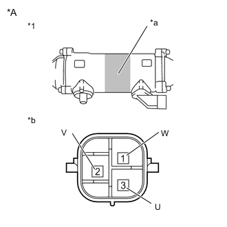
*A for RHD *1 Power Steering Link Assembly *a Area to Set Negative Probe *b Component without harness connected
(Power Steering Motor)
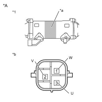
*A for LHD *1 Power Steering Link Assembly *a Area to Set Negative Probe *b Component without harness connected
(Power Steering Motor)
Measure the resistance according to the value(s) in the table below.
Standard Resistance Tester Connection Condition Specified Condition 1 (W) - 3 (U) Always 0.07 to 10 Ω 2 (V) - 1 (W) Always 0.07 to 10 Ω 3 (U) - 2 (V) Always 0.07 to 10 Ω 1 (W) - Power steering link housing* Always 100 kΩ or higher 2 (V) - Power steering link housing* Always 100 kΩ or higher 3 (U) - Power steering link housing* Always 100 kΩ or higher *: Touch the negative probe to the power steering link assembly housing at the position shown in the illustration to perform the measurement.
-
Disconnect the C3 torque sensor connector.
-
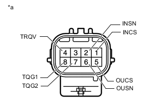
*a Component without harness connected
(Torque Sensor)
Measure the resistance according to the value(s) in the table below.
Standard Resistance Tester Connection Condition Specified Condition 1 (INCS) - 7 (TQG2) Always 90 to 170 Ω 2 (INSN) - 7 (TQG2) Always 300 to 430 Ω 4 (TRQV) - 8 (TQG1) Always 4 to 14 Ω 5 (OUCS) - 7 (TQG2) Always 90 to 170 Ω 6 (OUSN) - 7 (TQG2) Always 300 to 430 Ω -
Disconnect the C2 motor rotation angle sensor connector.
-
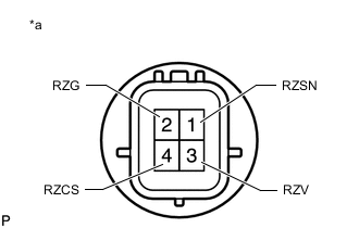
*a Component without harness connected
(Motor Rotation Angle Sensor)
Measure the resistance according to the value(s) in the table below.
Standard Resistance Tester Connection Condition Specified Condition 1 (RZSN) - 2 (RZG) Always 50 to 140 Ω 3 (RZV) - 2 (RZG) Always 15 to 45 Ω 4 (RZCS) - 2 (RZG) Always 50 to 140 Ω
-