PROCEDURE
- Click here
INSTALL POWER STEERING ECU ASSEMBLY
-
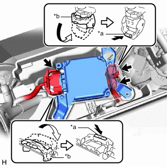
*a Lock of the Lock Lever *b Lock Lever Connect the 3 connectors to the power steering ECU assembly.
Tip:When connecting the connector with lock lever, return the lock lever to its original position and securely push in the lock of the lock lever as shown in the illustration.
-
Install the power steering ECU assembly to the battery tray with the 3 bolts.
8.5 N*m 87 kgf*cm 75 in.*lbf
-
- Click here
INSTALL NO. 1 BATTERY TRAY SUPPORT
-
Install the No. 1 battery tray support.
-
- Click here
INSTALL BATTERY
-
Install the battery and battery insulator.
-
Connect the 2 harness clamps.
-
Install the battery clamp with the nut.
2.9 N*m 30 kgf*cm 26 in.*lbf -
Connect the cable to the positive (+) battery terminal and tighten the nut.
5.5 N*m 56 kgf*cm 49 in.*lbf -
Engage the 2 claws to install the center No. 1 cowl top ventilator louver.
-
- Click here
CONNECT CABLE TO NEGATIVE BATTERY TERMINAL
-
Connect the cable to the negative (-) battery terminal and tighten the nut.
5.5 N*m 56 kgf*cm 49 in.*lbf Note:When disconnecting the cable, some systems need to be initialized after the cable is reconnected.
-
- Click here
ROTATION ANGLE SENSOR INITIALIZATION AND TORQUE SENSOR ZERO POINT CALIBRATION
- Click here
ASSIST MAP WRITING