DESCRIPTION
The characteristics of the electronic throttle, EPS and automatic transaxle change by operating the drive mode select switch (combination switch assembly).
PROCEDURE
- Click here
CHECK THE PROBLEM SYMPTOMS
-
Check each symptom by checking the suspected areas in the table below.
Result Result Proceed to SPORT, SPORT S/S+ mode or NORMAL mode is abnormal. A ECO mode is abnormal. B
- AClick here
- B
GO TO AIR CONDITIONING SYSTEMClick here
-
- Click here
CHECK CAN COMMUNICATION SYSTEM
-
Check for DTCs.
Result Result Proceed to CAN communication system DTCs are not output. A CAN communication system DTCs are output. B
- AClick here
- B
GO TO CAN COMMUNICATION SYSTEMClick here
-
- Click here
CHECK HARNESS AND CONNECTOR (DRIVE MODE SELECT SWITCH (COMBINATION SWITCH ASSEMBLY) - BODY GROUND)
-
Turn the engine switch off.
-
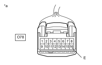
*a Front view of wire harness connector
(to Drive mode select switch (combination switch assembly))
Disconnect the O78 drive mode select switch (combination switch assembly) connector.
-
Measure the resistance according to the value(s) in the table below.
Standard Resistance Tester Connection Condition Specified Condition O78-16 (E) - Body ground Always Below 1 Ω Result Proceed to OK NG
- OKClick here
- NG
REPAIR OR REPLACE HARNESS OR CONNECTOR
-
- Click here
INSPECT DRIVE MODE SELECT SWITCH (COMBINATION SWITCH ASSEMBLY)
-
Inspect drive mode select switch (combination switch assembly).
OK Drive mode select switch (combination switch assembly) is normal. Result Proceed to OK NG
- OKClick here
- NG
REPLACE COMBINATION SWITCH ASSEMBLYClick here
-
- Click here
CHECK HARNESS AND CONNECTOR (DRIVE MODE SELECT SWITCH (COMBINATION SWITCH ASSEMBLY) - ECM)
-
Reconnect the O78 drive mode select switch (combination switch assembly) connector.
-
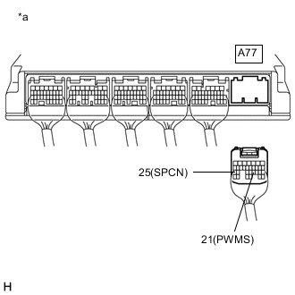
*a Rear view of wire harness connector
(to ECM)
Disconnect the A77 ECM connectors.
-
Measure the resistance according to the value(s) in the table below.
Standard Resistance Tester Connection Condition Specified Condition A77-21 (PWMS) - Body ground SPORT mode switch being turned and held Below 50 Ω A77-21 (PWMS) - Body ground SPORT mode switch not turned 10 kΩ or higher A77-25 (SPCN) - Body ground NORMAL mode switch being pushed and held Below 50 Ω A77-25 (SPCN) - Body ground NORMAL mode switch not pushed 10 kΩ or higher Result Proceed to OK NG
- OK
REPLACE ECMClick here
- NG
REPAIR OR REPLACE HARNESS OR CONNECTOR
-