DESCRIPTION
The power steering ECU assembly supplies current to the power steering motor.
| DTC No. | Detection Item | DTC Detection Condition | Trouble Area | Warning Indicate | Note |
|---|---|---|---|---|---|
| C1555 | Motor Relay Welding Failure | Motor relay circuit malfunction |
|
EPS warning light: Comes on | - |
CAUTION / NOTICE / HINT
-
If the power steering ECU assembly has been replaced, perform assist map writing, rotation angle sensor initialization and torque sensor zero point calibration.
-
If the power steering link assembly has been replaced, perform rotation angle sensor initialization and torque sensor zero point calibration for the power steering system.
PROCEDURE
- Click here
CHECK CONNECTORS
-
Check the connection of the power steering ECU assembly and power steering link assembly connectors.
-
Visually inspect the terminals of the power steering ECU assembly and power steering link assembly connectors.
Result Result Proceed to Normal A Connectors not properly connected B Power steering ECU assembly connector terminals abnormal C Power steering link assembly connector terminals abnormal D
- AClick here
- B
CONNECT CONNECTORS PROPERLY
- C
REPLACE POWER STEERING ECU ASSEMBLY for LHD:Click here
REPLACE POWER STEERING ECU ASSEMBLY for RHD:Click here
- D
REPLACE POWER STEERING LINK ASSEMBLYClick here
-
- Click here
CHECK HARNESS AND CONNECTOR (POWER STEERING ECU ASSEMBLY - POWER STEERING MOTOR)
-
Disconnect the C4 power steering ECU assembly connector.
-
Disconnect the C1 power steering motor connector.
-
Measure the resistance according to the value(s) in the table below.
Standard Resistance Tester Connection Condition Specified Condition C1-1 (W) - C4-2 (W) Always Below 1 Ω C1-2 (V) - C4-1 (V) Always Below 1 Ω C1-3 (U) - C4-3 (U) Always Below 1 Ω C1-1 (W) - Body ground Always 10 kΩ or higher C1-2 (V) - Body ground Always 10 kΩ or higher C1-3 (U) - Body ground Always 10 kΩ or higher Result Proceed to OK NG
- OKClick here
- NG
REPAIR OR REPLACE HARNESS OR CONNECTOR
-
- Click here
INSPECT POWER STEERING LINK ASSEMBLY (POWER STEERING MOTOR)
-
Disconnect the C1 power steering motor connector.
-
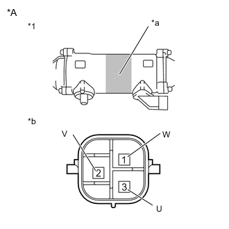
*A for RHD *1 Power Steering Link Assembly *a Area to Set Negative Probe *b Component without harness connected
(Power Steering Motor)
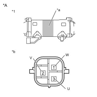
*A for LHD *1 Power Steering Link Assembly *a Area to Set Negative Probe *b Component without harness connected
(Power Steering Motor)
Measure the resistance according to the value(s) in the table below.
Standard Resistance Tester Connection Condition Specified Condition 1 (W) - 3 (U) Always 0.07 to 10 Ω 2 (V) - 1 (W) Always 0.07 to 10 Ω 3 (U) - 2 (V) Always 0.07 to 10 Ω 1 (W) - Power steering link housing* Always 100 kΩ or higher 2 (V) - Power steering link housing* Always 100 kΩ or higher 3 (U) - Power steering link housing* Always 100 kΩ or higher
-
*: Touch the negative probe to the power steering link assembly housing at the area shown in the illustration to perform the measurement.
Result Proceed to OK NG -
- OKClick here
- NG
REPLACE POWER STEERING LINK ASSEMBLYClick here
-
- Click here
CHECK POWER STEERING LINK ASSEMBLY (CHECK FOR CRACK IN RACK BOOTS)
CAUTION:If the rack boots are cracked, water may get into the power steering link assembly, resulting in a malfunction.
-
Remove the power steering link assembly.
-
Clean off any dirt or foreign matter attached to the rack boots.
-
Using SST, move the rack ends and check that there are no cracks in the rack boots.
OK There are no cracks. Tip:Using SST, turn the pinion shaft to move the rack ends.
09616-00011 Result Proceed to OK NG
- OK
REPLACE POWER STEERING ECU ASSEMBLY for LHD:Click here
REPLACE POWER STEERING ECU ASSEMBLY for RHD:Click here
- NG
REPLACE POWER STEERING LINK ASSEMBLYClick here
-