REAR BRAKE REMOVAL

CAUTION / NOTICE / HINT
Tech Tips
-
Use the same procedure for the RH side and LH side.
-
The following procedure is for the LH side.
PROCEDURE
-
REMOVE REAR WHEEL
-
DRAIN BRAKE FLUID
Note
If brake fluid leaks onto any painted surface, immediately wash it off.
-
REMOVE REAR DISC BRAKE PAD
Note
Be sure to inspect the rear disc when replacing the rear disc brake pads with new ones.
-
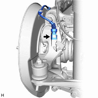
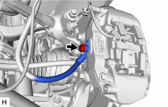
Disconnect the pad wear indicator wire connector from the rear speed sensor.
-
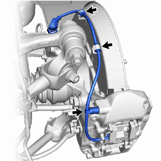
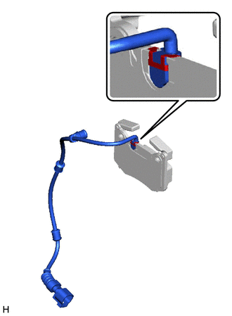
Disconnect the pad wear indicator wire assembly from the 2 clamps of rear disc brake dust cover.
-
Disconnect the bleeder plug cap portion of the pad wear indicator wire assembly from the rear disc brake bleeder plug.
-
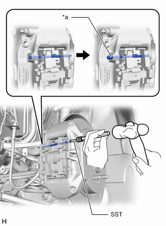
*a Ring Using SST and a hammer, disengage the ring of the pad guide pin (upper) and push out the pad guide pin (upper) from the rear disc brake cylinder assembly.
- SST
- 09719-77040
Note
-
Keep SST aligned with the pad guide pin (upper).
-
Do not damage the surface of the rear disc brake cylinder assembly.
-
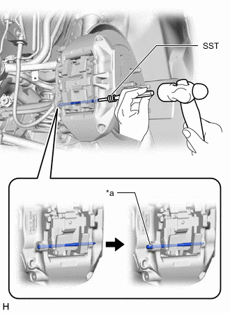
*a Ring Using SST and a hammer, disengage the ring of the pad guide pin (lower) and push out the pad guide pin (lower) from the rear disc brake cylinder assembly.
- SST
- 09719-77040
Note
-
Keep SST aligned with the pad guide pin (lower).
-
Do not damage the surface of the rear disc brake cylinder assembly.
-
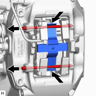
While pushing the rear disc brake anti-rattle spring as shown in the illustration, remove the 2 pad guide pins.
-
Remove the rear disc brake anti-rattle spring.
-
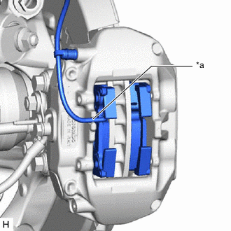
*a Notch Disengage the pad wear indicator wire assembly from the notch of the rear disc brake cylinder assembly.
-
Remove the 2 rear disc brake pads from the rear disc brake cylinder assembly.
-
Remove the pad wear indicator retainer and pad wear indicator wire assembly from the rear disc brake pad.
-
-
REMOVE REAR DISC BRAKE ANTI-SQUEAL SHIM KIT
-
Remove the rear disc brake anti-squeal shim from each rear disc brake pad.
-
-
DISCONNECT REAR FLEXIBLE HOSE
-
Remove the union bolt and gasket, and disconnect the rear flexible hose from the rear disc brake cylinder assembly.
-
-
REMOVE REAR DISC BRAKE CYLINDER ASSEMBLY
-
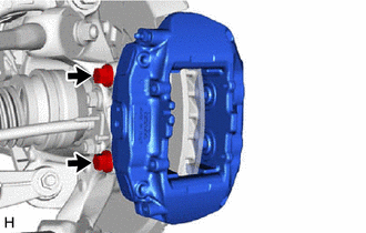
Remove the 2 bolts and rear disc brake cylinder assembly.
-
-
REMOVE PARKING BRAKE SHOE ADJUSTING HOLE PLUG
-
Remove the parking brake shoe adjusting hole plug.
-
-
REMOVE REAR DISC
-
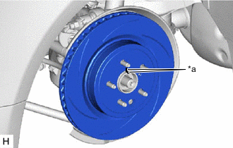
*a Matchmark Put matchmarks on the rear disc and the rear axle hub and bearing assembly.
-
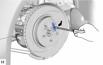

Contract Release the parking brake and remove the rear disc.
Tech Tips
If the rear disc cannot be removed easily, use a screwdriver to turn the shoe adjuster as shown in the illustration in order to contract the parking brake shoes.
-