FRONT BRAKE INSTALLATION

CAUTION / NOTICE / HINT
Tech Tips
-
Use the same procedure for the RH side and LH side.
-
The following procedure is for the LH side.
PROCEDURE
-
INSTALL FRONT DISC
-
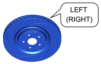
Check the identification mark to determine the installation side.
Note
The front disc needs to be installed to the correct side of the vehicle. There is a "LEFT", indicating the disc for the left wheel, or a "RIGHT", indicating the disc for the right wheel, engraved on the disc in the position shown in the illustration.
-
When reusing the front disc:
-
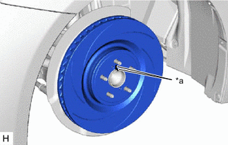
*a Matchmark Align the matchmarks of the front disc and front axle hub sub-assembly, and install the front disc.
-
-
When replacing the front disc:
-
Inspect the front disc runout.
-
Select the installation position where the front disc has minimal runout, and install the front disc.
-
-
Temporarily install the hub nut.
-
-
INSTALL FRONT DISC BRAKE CYLINDER ASSEMBLY
-
Install the front disc brake cylinder assembly to the steering knuckle with the 2 bolts.
- Torque:
- 135 N*m { 1377 kgf*cm, 100 ft.*lbf }
-
-
CONNECT FRONT FLEXIBLE HOSE
-
Connect the front flexible hose to the front disc brake cylinder assembly with a new union bolt and a new gasket.
- Torque:
- 39.2 N*m { 400 kgf*cm, 29 ft.*lbf }
Note
Install the front flexible hose lock securely into the lock hole in the front disc brake cylinder assembly.
-
-
INSTALL FRONT DISC BRAKE ANTI-SQUEAL SHIM KIT
-
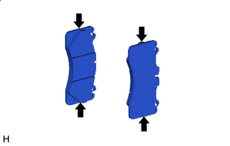

Grease Apply a light coat of disc brake grease to the front disc brake pads as shown in the illustration.
Note
-
When applying disc brake grease, use the grease enclosed with a front disc brake pad kit or supplied grease (Part No. 90998-94072) or equivalent.
-
There should be no oil or grease on the friction surfaces of the pads and the disc.
-
-
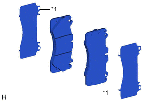
*1 Front Disc Brake Anti-squeal Shim Install the front disc brake anti-squeal shim to each front disc brake pad.
Note
When replacing the front disc brake pads with new ones, make sure to replace the front disc brake anti-squeal shim kit at the same time.
-
-
INSTALL FRONT DISC BRAKE PAD
-
Install the pad wear indicator wire assembly to the front disc brake pad (inner) with a new pad wear indicator retainer.
Note
When replacing the front disc brake pads with new ones, make sure to replace the pad wear indicator wire assembly and pad wear indicator retainer at the same time.
-
*a Notch Install the 2 front disc brake pads to the front disc brake cylinder assembly.
Note
The front disc brake pad with the pad wear indicator wire assembly must be installed to the inside position.
-
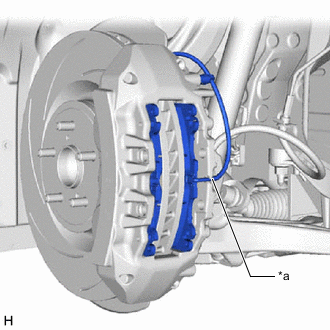
Insert the pad wear indicator wire assembly to the notch of the front disc brake cylinder assembly.
-
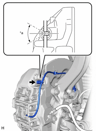
*a 0° +/- 30° Connect the bleeder plug cap portion of the pad wear indicator wire assembly to the front disc brake bleeder plug as shown in the illustration.
Note
Perform this step without the pad wear indicator wire assembly installed to the front disc brake dust cover clamp.
-
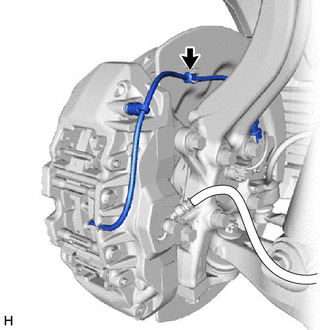
Connect the pad wear indicator wire assembly to the clamp of front disc brake dust cover.
-
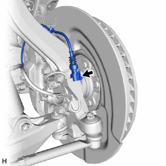
Connect the pad wear indicator wire connector to the front skid control sensor wire.
-
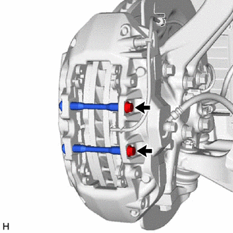
Install the 2 pad guide tie rods with the 2 bolts.
- Torque:
- 30 N*m { 306 kgf*cm, 22 ft.*lbf }
-
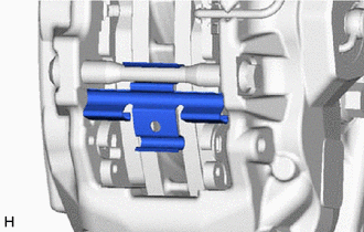
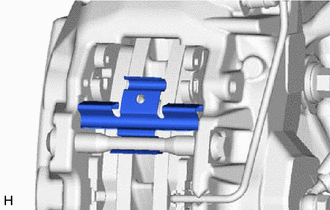
Install the front disc brake anti-rattle spring (lower) to the pad guide tie rod.
-
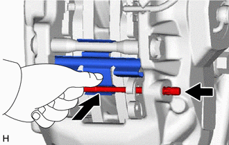
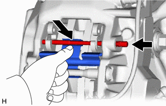
While pushing the front disc brake anti-rattle spring (lower) as shown in the illustration, install the pad guide pin (lower) to the front disc brake cylinder assembly.
-
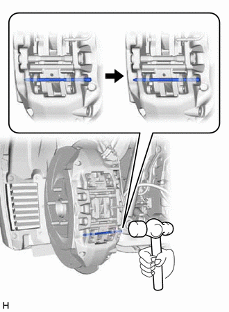
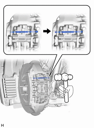
Using a hammer, install the pad guide pin (lower) by tapping the head of the pad guide pin (lower) until the ring is seated in the front disc brake cylinder assembly.
Note
-
Do not damage the surface of the front disc brake cylinder assembly.
-
Make sure that the ring of the pad guide pin (lower) is securely engaged with the front disc brake cylinder assembly.
-
Make sure that the front disc brake anti-rattle spring (lower) is securely installed into the grooves of the pad guide pin (lower).
-
-
Install the front disc brake anti-rattle spring (upper) to the pad guide tie rod.
-
While pushing the front disc brake anti-rattle spring (upper) as shown in the illustration, install the pad guide pin (upper) to the front disc brake cylinder assembly.
-
Using a hammer, install the pad guide pin (upper) by tapping the head of the pad guide pin (upper) until the ring is seated in the front disc brake cylinder assembly.
Note
-
Do not damage the surface of the front disc brake cylinder assembly.
-
Make sure that the ring of the pad guide pin (upper) is securely engaged with the front disc brake cylinder assembly.
-
Make sure that the front disc brake anti-rattle spring (upper) is securely installed into the grooves of the pad guide pin (upper).
-
-
-
BLEED BRAKE LINE
-
INSTALL FRONT WHEEL