| DTC Code | DTC Name |
|---|---|
| B15C4 | Airbag Signal Malfunction/Not Input |
DESCRIPTION
If the telematics transceiver detects an error in communication between the telematics transceiver and airbag ECU assembly as a result of the telematics transceiver self check, this DTC will be stored.
| DTC No. | Detection Item | DTC Detection Condition | Trouble Area |
|---|---|---|---|
| B15C4 | Airbag Signal Malfunction/Not Input | Airbag signal problem |
|
CAUTION / NOTICE / HINT
Depending on the parts that are replaced during vehicle inspection or maintenance, performing initialization, registration or calibration may be needed. Refer to Precaution for G-BOOK.
PROCEDURE
- Click here
CHECK DTC OUTPUT (AIRBAG SYSTEM)
-
Check for DTCs and check that no DTCs are output.
Result Result Proceed to No DTCs are output. A DTCs for airbag system are output. B
- AClick here
- B
GO TO AIRBAG SYSTEMClick here
-
- Click here
CHECK DTC OUTPUT
-
Clear the DTCs.
- Body Electrical > Navigation System > Clear DTCs
-
-
-
Recheck for DTCs and check if the same DTC is output again.
- Body Electrical > Navigation System > Trouble Codes
-
-
Result Result Proceed to No DTCs are output. A DTCs are output. B
- A
USE SIMULATION METHOD TO CHECKClick here
- BClick here
-
- Click here
CHECK HARNESS AND CONNECTOR (TELEMATICS TRANSCEIVER - AIRBAG ECU ASSEMBLY)
-
Disconnect the O65 telematics transceiver connector.
-
Disconnect the O50 airbag ECU assembly connector.
-
Measure the resistance according to the value(s) in the table below.
Standard Resistance Tester Connection Condition Specified Condition O65-24 (GSW) - O50-24 (GSW3) Always Below 1 Ω O65-24 (GSW) - Body ground Always 10 kΩ or higher Result Proceed to OK NG
- OKClick here
- NG
REPAIR OR REPLACE HARNESS OR CONNECTOR
-
- Click here
INSPECT TELEMATICS TRANSCEIVER
-
Disconnect the O65 telematics transceiver connector.
-
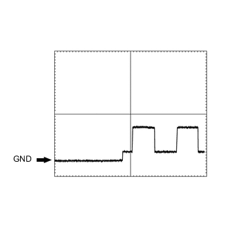
Check the input waveform.
-
Check the signal waveform according to the condition(s) in the table below. (Check the waveform from the back of the wire harness connector of the telematics transceiver while the airbag ECU assembly connectors are connected.)
Item Condition Tester Connection O65-24 (GSW) - Body ground Tool setting 5.0 V/DIV., 20 ms./DIV. Vehicle condition Engine switch on (IG) OK The waveform is similar to that shown in the illustration.
Result Proceed to OK NG -
- OK
REPLACE TELEMATICS TRANSCEIVERClick here
- NGClick here
-
- Click here
REPLACE AIRBAG ECU ASSEMBLY
-
Replace the airbag ECU assembly.
Result Proceed to NEXT
- NEXTClick here
-
- Click here
CHECK DTC OUTPUT
-
Clear the DTCs.
- Body Electrical > Navigation System > Clear DTCs
-
-
-
Recheck for DTCs and check if the same DTC is output again.
- Body Electrical > Navigation System > Trouble Codes
-
-
Result Result Proceed to No DTCs are output. A DTCs are output. B
- A
END
- B
REPLACE TELEMATICS TRANSCEIVERClick here
-