TELEMATICS SYSTEM, Diagnostic DTC:B15C5
| DTC Code | DTC Name |
|---|---|
| B15C5 | Manual Button Malfunction |
DESCRIPTION
If the telematics transceiver detects an error in the communication between the telematics transceiver and the map light assembly (emergency call switch) as a result of the telematics transceiver self check, this DTC will be stored.
| DTC No. | Detection Item | DTC Detection Condition | Trouble Area |
|---|---|---|---|
| B15C5 | Manual Button Malfunction | A problem with the emergency call switch is detected |
|
WIRING DIAGRAM
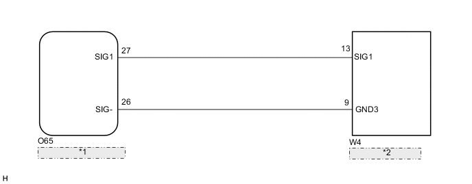
| *1 | Telematics Transceiver |
| *2 | Map Light Assembly |
CAUTION / NOTICE / HINT
Note
Depending on the parts that are replaced during vehicle inspection or maintenance, performing initialization, registration or calibration may be needed. Refer to Precaution for G-BOOK.
PROCEDURE
-
CHECK DTC OUTPUT
-
Clear the DTCs.
Body Electrical > Navigation System > Clear DTCs -
Recheck for DTCs and check if the same DTC is output again.
Body Electrical > Navigation System > Trouble CodesResult Result Proceed to No DTCs are output. A DTCs are output. B
A 
USE SIMULATION METHOD TO CHECK Click here
B 
-
-
INSPECT MAP LIGHT ASSEMBLY
-
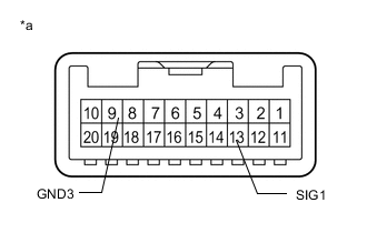
*a Component without harness connected
(Map Light Assembly)
Remove the map light assembly.
-
Measure the resistance according to the value(s) in the table below.
Standard Resistance Tester Connection Condition Specified Condition 13 (SIG1) - 9 (GND3) Emergency call switch not operated 410 to 414 Ω 13 (SIG1) - 9 (GND3) Emergency call switch operated 81 to 83 Ω Result Proceed to OK NG
NG
REPLACE MAP LIGHT ASSEMBLY Click here
OK
-
-
CHECK HARNESS AND CONNECTOR (TELEMATICS TRANSCEIVER - MAP LIGHT ASSEMBLY)
-
Disconnect the O65 telematics transceiver connector.
-
Disconnect the W4 map light assembly connector.
-
Measure the resistance according to the value(s) in the table below.
Standard Resistance Tester Connection Condition Specified Condition O65-27 (SIG1) - W4-13 (SIG1) Always Below 1 Ω O65-26 (SIG-) - W4-9 (GND3) Always Below 1 Ω O65-27 (SIG1) - Body ground Always 10 kΩ or higher O65-26 (SIG-) - Body ground Always 10 kΩ or higher Result Proceed to OK NG
OK
REPLACE TELEMATICS TRANSCEIVER Click here
NG
REPAIR OR REPLACE HARNESS OR CONNECTOR
-