PROCEDURE
- Click here
INSTALL REAR SUSPENSION MEMBER FRONT BODY MOUNTING CUSHION (for LH Side)
-
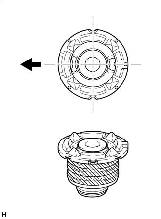

Front of the Vehicle 
Diluted Liquid Soap Apply diluted liquid soap to the outside of a new rear suspension member front body mounting cushion.
Note:Do not use grease or undiluted liquid soap. Doing so may cause the rear suspension member front body mounting cushion to slip out.
Tip:A 20% liquid soap and water concentration is recommended.
-
Temporarily install the rear suspension member front body mounting cushion while confirming the installation direction.
-

*a Turn *b Hold Using SST, install the rear suspension member front body mounting cushion until there is no clearance between the rear suspension member sub-assembly and rear suspension member front body mounting cushion.
09950-40011 09951-04020 09952-04010 09953-04030 09954-04020 09955-04051 09957-04010 09958-04011 09950-60020 09951-00910 09570-24011 Note:Apply grease to the threads and tip of the SST center bolt before use.
-
- Click here
INSTALL REAR SUSPENSION MEMBER FRONT BODY MOUNTING CUSHION (for RH Side)
Tip:Perform the same procedure as for the LH side.
- Click here
INSTALL REAR SUSPENSION MEMBER REAR BODY MOUNTING CUSHION (for LH Side)
-
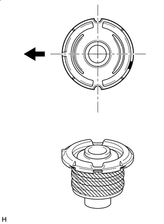
Front of the Vehicle Diluted Liquid Soap Apply diluted liquid soap to the outside of a new rear suspension member rear body mounting cushion.
Note:Do not use grease or undiluted liquid soap. Doing so may cause the rear suspension member rear body mounting cushion to slip out.
Tip:A 20% liquid soap and water concentration is recommended.
-
Temporarily install the rear suspension member rear body mounting cushion while confirming the installation direction.
-
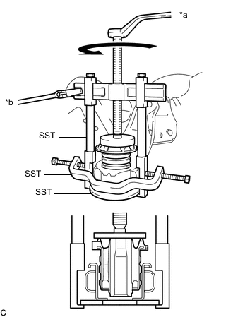
*a Turn *b Hold Using SST, install the rear suspension member rear body mounting cushion until there is no clearance between the rear suspension member sub-assembly and rear suspension member rear body mounting cushion.
09950-40011 09951-04020 09952-04010 09953-04030 09954-04020 09955-04051 09957-04010 09958-04011 09950-60020 09951-00910 09570-24011 Note:Apply grease to the threads and tip of the SST center bolt before use.
-
- Click here
INSTALL REAR SUSPENSION MEMBER REAR BODY MOUNTING CUSHION (for RH Side)
Tip:Perform the same procedure as for the LH side.
- Click here
INSTALL REAR SUSPENSION MEMBER REAR LOWER STOPPER (for LH Side)
-
Install the rear suspension member rear lower stopper to the rear suspension member sub-assembly.
-
- Click here
INSTALL REAR SUSPENSION MEMBER REAR LOWER STOPPER (for RH Side)
Tip:Perform the same procedure as for the LH side.
- Click here
INSTALL REAR SUSPENSION MEMBER REAR UPPER STOPPER (for LH Side)
-
Install the rear suspension member rear upper stopper to the rear suspension member sub-assembly.
-
- Click here
INSTALL REAR SUSPENSION MEMBER REAR UPPER STOPPER (for RH Side)
Tip:Perform the same procedure as for the LH side.
- Click here
INSTALL REAR NO. 1 DIFFERENTIAL MOUNT CUSHION
- Click here
INSTALL REAR NO. 2 DIFFERENTIAL MOUNT CUSHION
- Click here
INSTALL REAR STABILIZER BAR SUB-ASSEMBLY
-
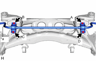
*a Identification Mark Install the rear stabilizer bar sub-assembly with 2 rear No. 1 stabilizer bar brackets to the rear suspension member sub-assembly with the 4 bolts.
51 N*m 520 kgf*cm 38 ft.*lbf Note:
-
Temporarily tighten the bolt (A), and then fully tighten the 4 bolts in the order of (B), (C), (D), and (A).
-
Ensure that the identification mark is on the right side of the vehicle.
-
-
- Click here
INSTALL REAR NO. 2 UPPER CONTROL ARM ASSEMBLY LH
- Click here
INSTALL REAR NO. 2 UPPER CONTROL ARM ASSEMBLY RH
Tip:Perform the same procedure as for the LH side.
- Click here
INSTALL REAR NO. 1 UPPER CONTROL ARM ASSEMBLY LH
- Click here
INSTALL REAR NO. 1 UPPER CONTROL ARM ASSEMBLY RH
Tip:Perform the same procedure as for the LH side.
- Click here
INSTALL REAR DIFFERENTIAL CARRIER ASSEMBLY (for LSD)
- Click here
INSTALL TORQUE VECTORING DIFFERENTIAL FDU (FINAL DRIVE UNIT) (for Torque Vectoring Differential)
- Click here
INSTALL REAR SUSPENSION ARM BRACKET ASSEMBLY
- Click here
INSTALL NO. 4 FLOOR WIRE (for Torque Vectoring Differential)
- Click here
INSTALL REAR SUSPENSION MEMBER SUB-ASSEMBLY
-
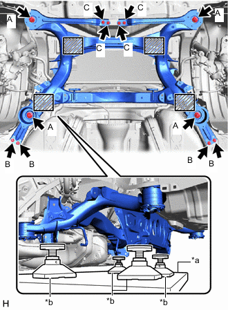
*a Engine Lifter *b Attachment Attachment placement location Support the rear suspension member sub-assembly with an engine lifter using 4 attachments or equivalent tools as shown in the illustration.
CAUTION:Make sure to secure the rear suspension member sub-assembly to prevent it from dropping.
Note:
-
Use attachments to keep the rear suspension member sub-assembly level.
-
The rear suspension member sub-assembly is a heavy component. Make sure that it is supported securely.
-
-
Raise the rear suspension member sub-assembly until there is no clearance between the rear suspension member sub-assembly and vehicle body.
Note:When raising the rear suspension member sub-assembly, be careful not to damage the vehicle body or other components installed to the vehicle.
-
Install the rear suspension member sub-assembly with the rear floor panel brace sub-assembly LH, rear floor panel brace sub-assembly RH, rear suspension member lower stopper sub-assembly LH and rear suspension member lower stopper sub-assembly RH with the 4 bolts (A), 4 bolts (B) and 4 bolts (C).
Bolt (A) 127 N*m 1295 kgf*cm 94 ft.*lbf Bolt (B) 19 N*m 194 kgf*cm 14 ft.*lbf Bolt (C) 19 N*m 194 kgf*cm 14 ft.*lbf
-
- Click here
CONNECT NO. 4 FLOOR WIRE (for Torque Vectoring Differential)
- Click here
INSTALL REAR BODY MOUNTING CUSHION SUB-ASSEMBLY LH
-
Install the rear body mounting cushion sub-assembly LH with the 4 bolts.
19 N*m 194 kgf*cm 14 ft.*lbf
-
- Click here
INSTALL REAR BODY MOUNTING CUSHION SUB-ASSEMBLY RH
Tip:Perform the same procedure as for the LH side.
- Click here
INSTALL REAR DRIVE SHAFT ASSEMBLY LH
- Click here
INSTALL REAR DRIVE SHAFT ASSEMBLY RH
Tip:Use the same procedure as for the LH side.
- Click here
INSTALL REAR AXLE ASSEMBLY LH
- Click here
INSTALL REAR AXLE ASSEMBLY RH
Tip:Perform the same procedure as for the LH side.
- Click here
CONNECT REAR NO. 2 UPPER CONTROL ARM ASSEMBLY LH
-
Temporarily install the rear No. 2 upper control arm assembly LH to the rear axle assembly LH with the bolt, nut and washer.
Note:Because the bolt has its own stopper, do not turn the bolt. Tighten the nut with the bolt secured.
Tip:Insert the bolt with the threaded end facing the rear of the vehicle.
-
- Click here
CONNECT REAR NO. 2 UPPER CONTROL ARM ASSEMBLY RH
Tip:Perform the same procedure as for the LH side.
- Click here
CONNECT REAR NO. 1 UPPER CONTROL ARM ASSEMBLY LH
-
Temporarily install the rear No. 1 upper control arm assembly LH to the rear axle assembly LH with the bolt, nut and washer.
Note:Because the bolt has its own stopper, do not turn the bolt. Tighten the nut with the bolt secured.
Tip:Insert the bolt with the threaded end facing the front of the vehicle.
-
- Click here
CONNECT REAR NO. 1 UPPER CONTROL ARM ASSEMBLY RH
Tip:Perform the same procedure as for the LH side.
- Click here
TEMPORARILY INSTALL REAR NO. 2 SUSPENSION ARM ASSEMBLY LH
- Click here
TEMPORARILY INSTALL REAR NO. 2 SUSPENSION ARM ASSEMBLY RH
Tip:Perform the same procedure as for the LH side.
- Click here
INSTALL REAR LOWER COIL SPRING INSULATOR LH
- Click here
INSTALL REAR LOWER COIL SPRING INSULATOR RH
Tip:Perform the same procedure as for the LH side.
- Click here
INSTALL REAR UPPER COIL SPRING INSULATOR LH
- Click here
INSTALL REAR UPPER COIL SPRING INSULATOR RH
Tip:Perform the same procedure as for the LH side.
- Click here
INSTALL REAR COIL SPRING LH
- Click here
INSTALL REAR COIL SPRING RH
Tip:Perform the same procedure as for the LH side.
- Click here
TEMPORARILY INSTALL REAR SHOCK ABSORBER ASSEMBLY LH
- Click here
TEMPORARILY INSTALL REAR SHOCK ABSORBER ASSEMBLY RH
Tip:Perform the same procedure as for the LH side.
- Click here
INSTALL REAR STABILIZER LINK ASSEMBLY LH
- Click here
INSTALL REAR STABILIZER LINK ASSEMBLY RH
Tip:Perform the same procedure as for the LH side.
- Click here
INSTALL REAR SUSPENSION MEMBER BRACE LH
- Click here
INSTALL REAR SUSPENSION MEMBER BRACE RH
Tip:Perform the same procedure as for the LH side.
- Click here
TEMPORARILY INSTALL REAR NO. 1 SUSPENSION ARM ASSEMBLY LH
- Click here
TEMPORARILY INSTALL REAR NO. 1 SUSPENSION ARM ASSEMBLY RH
Tip:Perform the same procedure as for the LH side.
- Click here
CONNECT REAR STEERING TIE ROD ASSEMBLY LH
- Click here
CONNECT REAR STEERING TIE ROD ASSEMBLY RH
Tip:Perform the same procedure as for the LH side.
- Click here
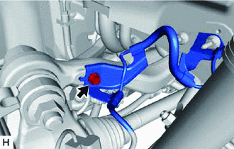
INSTALL NO. 3 PARKING BRAKE CABLE ASSEMBLY
-
Install the No. 3 parking brake cable assembly to the rear suspension member sub-assembly with the 2 bolts.
19 N*m 194 kgf*cm 14 ft.*lbf
-
- Click here
INSTALL NO. 2 PARKING BRAKE CABLE ASSEMBLY
Tip:Perform the same procedure as for the No. 3 parking brake cable assembly.
- Click here
INSTALL PARKING BRAKE ASSEMBLY (for LH Side)
- Click here
INSTALL PARKING BRAKE ASSEMBLY (for RH Side)
Tip:Perform the same procedure as for the LH side.
- Click here
INSTALL REAR SPEED SENSOR LH
- Click here
INSTALL REAR SPEED SENSOR RH
Tip:Perform the same procedure as for the LH side.
- Click here
INSTALL REAR DISC LH
- Click here
INSTALL REAR DISC RH
Tip:Perform the same procedure as for the LH side.
- Click here
INSTALL PARKING BRAKE SHOE ADJUSTING HOLE PLUG
-
Install the 2 parking brake shoe adjusting hole plugs.
-
- Click here
INSTALL REAR DISC BRAKE CALIPER ASSEMBLY LH
- Click here
INSTALL REAR DISC BRAKE CALIPER ASSEMBLY RH
Tip:Perform the same procedure as for the LH side.
- Click here
ADJUST PARKING BRAKE
- Click here
TEMPORARILY INSTALL REAR AXLE SHAFT NUT LH
- Click here
TEMPORARILY INSTALL REAR AXLE SHAFT NUT RH
Tip:Perform the same procedure as for the LH side.
- Click here
INSTALL REAR AXLE SHAFT NUT LH
- Click here
INSTALL REAR AXLE SHAFT NUT RH
Tip:Perform the same procedure as for the LH side.
- Click here
STABILIZE SUSPENSION
- Click here
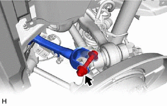
INSTALL REAR NO. 2 UPPER CONTROL ARM ASSEMBLY LH
-

Install the rear No. 2 upper control arm assembly LH (rear axle assembly side) with the nut.
190 N*m 1937 kgf*cm 140 ft.*lbf Note:Because the bolt has its own stopper, do not turn the bolt. Tighten the nut with the bolt secured.
-
Install the rear speed sensor LH to the rear No. 2 upper control arm assembly LH with the bolt.
8.5 N*m 87 kgf*cm 75 in.*lbf
-
- Click here
INSTALL REAR NO. 2 UPPER CONTROL ARM ASSEMBLY RH
Tip:Perform the same procedure as for the LH side.
- Click here
INSTALL REAR NO. 1 UPPER CONTROL ARM ASSEMBLY LH
-
Install the rear No. 1 upper control arm assembly LH (rear axle assembly side) with the nut.
150 N*m 1530 kgf*cm 111 ft.*lbf Note:Because the bolt has its own stopper, do not turn the bolt. Tighten the nut with the bolt secured.
-
- Click here
INSTALL REAR NO. 1 UPPER CONTROL ARM ASSEMBLY RH
Tip:Perform the same procedure as for the LH side.
- Click here
INSTALL REAR NO. 2 SUSPENSION ARM ASSEMBLY LH
- Click here
INSTALL REAR NO. 2 SUSPENSION ARM ASSEMBLY RH
Tip:Perform the same procedure as for the LH side.
- Click here
INSTALL REAR SHOCK ABSORBER ASSEMBLY LH
- Click here
INSTALL REAR SHOCK ABSORBER ASSEMBLY RH
Tip:Perform the same procedure as for the LH side.
- Click here
INSTALL REAR NO. 1 SUSPENSION ARM ASSEMBLY LH
- Click here
INSTALL REAR NO. 1 SUSPENSION ARM ASSEMBLY RH
Tip:Perform the same procedure as for the LH side.
- Click here
INSTALL REAR HEIGHT CONTROL SENSOR SUB-ASSEMBLY
- Click here
INSTALL REAR SUSPENSION ARM COVER LH
- Click here
INSTALL REAR SUSPENSION ARM COVER RH
Tip:Perform the same procedure as for the LH side.
- Click here
CONNECT TAIL EXHAUST PIPE LH
- Click here
CONNECT TAIL EXHAUST PIPE ASSEMBLY
- Click here
INSTALL PROPELLER WITH CENTER BEARING SHAFT ASSEMBLY
- Click here
INSTALL FRONT CENTER FLOOR BRACE
-
Install the front center floor brace with the 6 bolts, 2 nuts and 2 clips.
19 N*m 194 kgf*cm 14 ft.*lbf
-
- Click here
INSTALL NO. 1 FLOOR UNDER COVER ASSEMBLY
-
Install the No. 1 floor under cover assembly with the 4 clips and 5 grommets.
-
- Click here
INSTALL FRONT CENTER FLOOR COVER LH
-
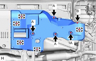
Install the front center floor cover LH with the 4 clips (A), clip (B) and 5 clamps.
-
- Click here
INSTALL FRONT CENTER FLOOR COVER RH
Tip:Perform the same procedure as for the LH side.
- Click here
INSTALL REAR WHEEL
- Click here
INSPECT AND ADJUST REAR WHEEL ALIGNMENT
- Click here
CHECK FOR SPEED SENSOR SIGNAL