PROCEDURE
- Click here
REMOVE REAR WHEEL
- Click here
SEPARATE REAR STEERING TIE ROD ASSEMBLY LH
-
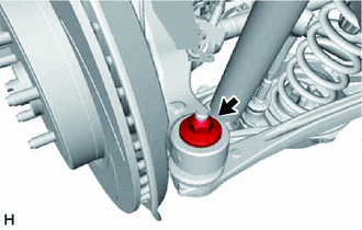
Remove the nut.
-
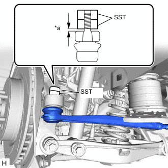
*a 1 mm or more Install 2 spacers (SST spacer B) as shown in the illustration.
09960-20010 09961-02060 Note:Make sure that the clearance between the rear axle assembly and spacers (SST spacer B) is 1 mm (0.0394 in.) or more to prevent damage to SST.
-
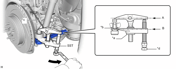
*a Nut *b Spacer *c Tie string without any slack *d Place wrench here 
Turn 
Molybdenum Grease Using SST, separate the rear steering tie rod assembly LH from the rear axle assembly as shown in the illustration.
09960-20010 09961-02010 09961-02060 CAUTION:Apply molybdenum grease to the threads and tip of the SST bolt.
Note:
-
Install SST so that A and B are parallel.
-
Be sure to place the wrench on the part indicated in the illustration.
-
Be sure to tighten the string firmly to secure SST to the rear No. 2 upper control arm assembly LH to prevent SST from falling off.
-
Do not damage the rear steering tie rod assembly LH ball joint dust cover.
-
Make sure that SST is securely positioned on the spacer.
-
If the spacer has come off, replace the rear axle carrier sub-assembly with a new one.
-
-
- Click here
SEPARATE REAR STEERING TIE ROD ASSEMBLY RH
Tip:Perform the same procedure as for the LH side.
- Click here
REMOVE REAR SUSPENSION MEMBER SUB-ASSEMBLY
- Click here
REMOVE REAR SUSPENSION ARM BRACKET ASSEMBLY
-
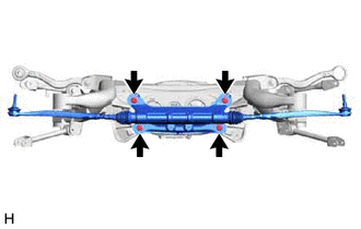
Remove the 4 bolts and rear suspension arm bracket assembly.
Note:Do not drop the rear suspension arm bracket assembly.
-
- Click here
REMOVE REAR STEERING TIE ROD ASSEMBLY LH
-
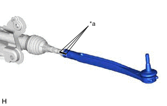
*a Matchmark Put matchmarks on the rear steering tie rod assembly LH, lock nut and steering rack end.
-
Remove the rear steering tie rod assembly LH and lock nut.
-
- Click here
REMOVE REAR STEERING TIE ROD ASSEMBLY RH
Tip:Perform the same procedure as for the LH side.