CAUTION / NOTICE / HINT
-
Use the same procedure for the RH side and LH side.
-
The following procedure is for the LH side.
PROCEDURE
- Click here
INSTALL REAR LOWER COIL SPRING INSULATOR
-
Install the rear lower coil spring insulator to the rear No. 2 suspension arm assembly.
-
- Click here
INSTALL REAR UPPER COIL SPRING INSULATOR
-
Install the rear upper coil spring insulator to the rear coil spring.
-
- Click here
INSTALL REAR COIL SPRING
-
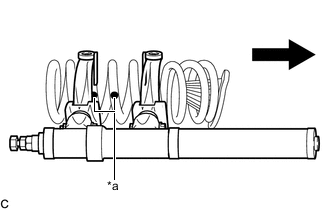
*a Identification Mark 
Upper Side Install SST to the rear coil spring with the identification marks on the rear coil spring positioned as shown in illustration.
09727-30022 09727-00010 09727-00031 09727-00120 CAUTION:
-
Make sure that the arms of SST are parallel and attached to the coil spring, and the number of coil springs between the hooks on each side is the same.
-
Check that the claws of the hooks are securely attached to the coil spring.
-
-
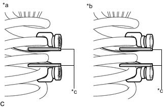
*a Correct *b Incorrect *c Stopper plate Install the stopper plates to the hooks of SST.
CAUTION:Make sure that the stopper plates are installed securely.
-
Using SST, compress the rear coil spring.
CAUTION:
-
If the coil spring bends while using SST, stop immediately and reattach SST correctly.
-
Do not compress the coil spring to the point where the coils touch each other.
-
Do not use an impact wrench.
-
-
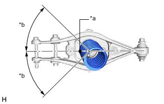
*a Identification Mark *b 45° or less Temporarily install the rear coil spring with SST and rear upper coil spring insulator to the rear No. 2 suspension arm assembly.
Note:
-
Make sure to install the rear coil spring with the identification mark facing downward.
-
Install the rear coil spring so that the identification mark is positioned as shown in the illustration.
-
If SST contacts the vehicle body, adjust the installation position of SST so that it does not contact the vehicle body.
-
-
Using a transmission jack and wooden block, slowly jack up the rear No. 2 suspension arm assembly and then temporarily install the rear No. 2 suspension arm assembly to the rear axle assembly with the bolt and nut.
CAUTION:Do not jack up the rear No. 2 suspension arm assembly too high as the vehicle may fall.
Note:
-
Because the nut has its own stopper, do not turn the nut. Tighten the bolt with the nut secured.
-
When jacking up the rear No. 2 suspension arm assembly, be sure to jack it up slowly.
-
Make sure to perform this operation with the vehicle kept as low as possible.
Tip:Insert the bolt with the threaded end facing the front of the vehicle.
-
-
Remove SST from the rear coil spring.
Note:Do not use an impact wrench. It will damage SST.
-
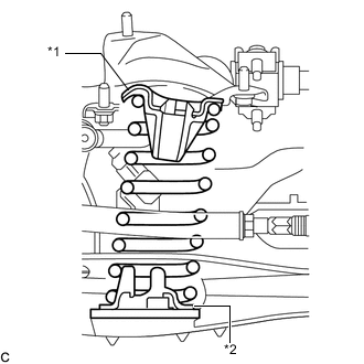
*1 Rear Upper Coil Spring Insulator *2 Rear Lower Coil Spring Insulator Check that the rear upper coil spring insulator and rear lower coil spring insulator are installed as shown in the illustration.
-
- Click here
TEMPORARILY INSTALL REAR SHOCK ABSORBER ASSEMBLY
-
Temporarily install the rear shock absorber assembly to the rear No. 2 suspension arm assembly with the bolt and nut.
Note:Because the nut has its own stopper, do not turn the nut. Tighten the bolt with the nut secured.
Tip:Insert the bolt with the threaded end facing the front of the vehicle.
-
- Click here
INSTALL REAR STABILIZER LINK ASSEMBLY
- Click here
TEMPORARILY INSTALL REAR NO. 1 SUSPENSION ARM ASSEMBLY
-
Temporarily install the rear No. 1 suspension arm assembly to the rear axle assembly with the bolt and nut.
Note:Because the nut has its own stopper, do not turn the nut. Tighten the bolt with the nut secured.
Tip:Insert the bolt with the threaded end facing the front of the vehicle.
-
- Click here
CONNECT REAR STEERING TIE ROD ASSEMBLY
- Click here
STABILIZE SUSPENSION
- Click here
INSTALL REAR NO. 2 SUSPENSION ARM ASSEMBLY
-
Install the rear No. 2 suspension arm assembly (rear axle assembly side) with the bolt.
145 N*m 1479 kgf*cm 107 ft.*lbf Note:Because the nut has its own stopper, do not turn the nut. Tighten the bolt with the nut secured.
-
- Click here
INSTALL REAR SHOCK ABSORBER ASSEMBLY
- Click here
INSTALL REAR NO. 1 SUSPENSION ARM ASSEMBLY
-
Install the rear No. 1 suspension arm assembly (rear axle assembly side) with the bolt.
90 N*m 918 kgf*cm 66 ft.*lbf Note:Because the nut has its own stopper, do not turn the nut. Tighten the bolt with the nut secured.
-
- Click here
INSTALL REAR HEIGHT CONTROL SENSOR SUB-ASSEMBLY
-
Install the rear height control sensor sub-assembly to the rear No. 1 upper control arm assembly with the nut.
8.0 N*m 82 kgf*cm 71 in.*lbf
-
- Click here
INSTALL REAR SUSPENSION ARM COVER
- Click here
INSTALL REAR WHEEL
- Click here
INSPECT AND ADJUST REAR WHEEL ALIGNMENT
- Click here
INITIALIZE HEIGHT CONTROL SENSOR SIGNAL
- Click here
ADJUST HEADLIGHT AIMING