CAUTION / NOTICE / HINT
-
Use the same procedure for the RH side and LH side.
-
The following procedure is for the LH side.
PROCEDURE
- Click here
INSTALL FRONT COIL SPRING
-
For SST with stopper pins:
-
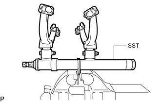
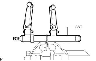
Secure SST in a vise.
09727-30022 09727-00010 09727-00022 09727-00031 -
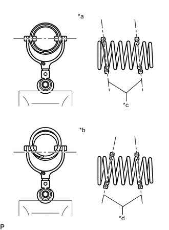
*a Correct *b Incorrect *c Parallel *d Not Parallel Attach the hooks of each SST arm across the diameter of the coil spring.
CAUTION:
-
Make sure that the hooks of the upper and lower arms are attached to the coil spring so that the distance between the hooks is as large as possible.
-
Make sure that the arms of SST are parallel and attached to the coil spring, and the number of coil springs between the hooks on each side is the same.
-
Check that the claws of the hooks are securely attached to the coil spring.
-
-
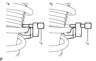
*a Correct *b Incorrect *c Stopper Pin Install the stopper pins to the hooks of SST.
CAUTION:Make sure that the stopper pins are installed securely.
-
Using SST, compress the coil spring.
CAUTION:
-
If the coil spring bends while using SST, stop immediately and reattach SST correctly.
-
Do not compress the coil spring to the point where the coils touch each other.
-
Do not use an impact wrench.
-
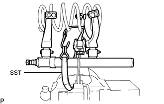
If a stopper pin touches the coil spring while using SST, remove the stopper pin and continue with the procedure. In this case, installing the coil spring stopper belt as shown in the illustration is recommended.
09727-00110 -
-
-
For SST without stopper pins:
-
Secure SST in a vise.
09727-30021 09727-00010 09727-00021 09727-00031 -
*a Correct *b Incorrect *c Parallel *d Not Parallel Attach the hooks of each SST arm across the diameter of the coil spring.
CAUTION:
-
Make sure that the hooks of the upper and lower arms are attached to the coil spring so that the distance between the hooks is as large as possible.
-
Make sure that the arms of SST are parallel and attached to the coil spring, and the number of coil springs between the hooks on each side is the same.
-
Check that the claws of the hooks are securely attached to the coil spring.
-
-
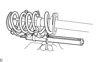
Using SST, compress the coil spring.
CAUTION:
-
If the coil spring bends while using SST, stop immediately and reattach SST correctly.
-
Do not compress the coil spring to the point where the coils touch each other.
-
Do not use an impact wrench.
Tip: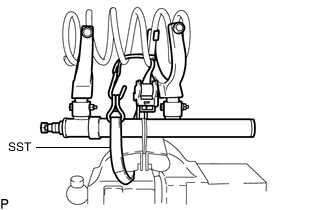
Installing SST as shown in the illustration is recommended.
09727-00110 -
-
-
Install the front coil spring to the front shock absorber assembly.
-
Install the front spring bumper to the front suspension support assembly.
-
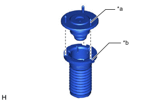
*a Bolt *b Cutout Install the front upper coil spring insulator to the front suspension support assembly as shown in the illustration.
Note:Align the bolt of the front suspension support assembly and the cutout of the front upper coil spring insulator.
-
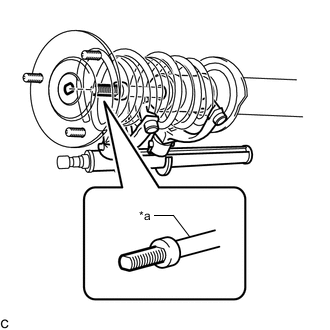
*a Piston Rod Install the front suspension support assembly to the front shock absorber assembly.
Note:Match the shape of the front shock absorber assembly piston rod end to the shape of the front suspension support assembly.
-
Temporarily tighten a new lock nut.
-
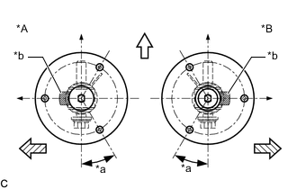
*A LH Side *B RH Side *a 30° +/- 2° *b Identification Mark 
Front of the Vehicle 
Outside of the Vehicle Adjust the front suspension support assembly so that the bolts come to the positions as shown in the illustration, and remove SST from the front coil spring.
Note:
-
Do not use an impact wrench. It will damage SST.
-
Make sure that the flat surface of the threads of the front shock absorber piston rod end is parallel to the front shock absorber bushing.
-
Make sure that the front suspension support assembly is aligned as shown in the illustration when removing SST.
-
-
- Click here
TEMPORARILY TIGHTEN FRONT SHOCK ABSORBER WITH COIL SPRING
-
Temporarily tighten the front shock absorber with coil spring (upper side) to the vehicle body with the 3 nuts.
-
Temporarily tighten the front shock absorber with coil spring (lower side) to the front lower suspension arm assembly with the bolt and nut.
Note:
-
Insert the bolt from the rear of the vehicle.
-
Because the nut has its own stopper, do not turn the nut. Tighten the bolt with the nut secured.
Tip:Fully tighten the bolt after stabilizing the suspension.
-
-
Fully tighten the lock nut.
27.5 N*m 280 kgf*cm 20 ft.*lbf Note:Perform this step only when the front shock absorber with coil spring has been disassembled.
-
Remove the 3 nuts from the front shock absorber with coil spring (upper side).
-
Install the front shock absorber with coil spring (upper side) and front upper suspension to cowl brace sub-assembly with the 3 nuts.
67 N*m 683 kgf*cm 49 ft.*lbf
-
- Click here
INSTALL FRONT UPPER SUSPENSION ARM ASSEMBLY
-
Install the front upper suspension arm assembly to the steering knuckle with the nut.
87 N*m 887 kgf*cm 64 ft.*lbf Note:Prevent oil from adhering to the threaded and tapered parts.
-
Install a new clip.
Note:Further tighten the nut up to 60° if the holes for the clip are not aligned.
-
- Click here
INSTALL FRONT STABILIZER LINK SUB-ASSEMBLY
- Click here
INSTALL FRONT SKID CONTROL SENSOR WIRE
-
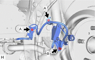
Install the front skid control sensor wire to the steering knuckle, front shock absorber with coil spring and vehicle body with the 3 bolts.
Bolt (A) 6.0 N*m 61 kgf*cm 53 in.*lbf Bolt (B) 8.5 N*m 87 kgf*cm 75 in.*lbf Note:
-
Be careful not to deform the bracket of the front shock absorber with coil spring when installing the bolt.
-
Do not twist the front skid control sensor wire when installing it.
-
-
Connect the front skid control sensor wire connector to the front axle hub sub-assembly.
Note:Do not twist the front skid control sensor wire when installing it.
-
Connect the pad wear indicator wire connector to the front skid control sensor wire clamp.
Note:Do not twist the pad wear indicator wire when installing it.
-
- Click here
STABILIZE SUSPENSION
-
Install the front wheel.
-
Lower the vehicle and bounce it up and down several times to stabilize the front suspension.
-
Remove the front wheel.
-
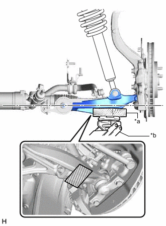
*a Wooden Block *b Jack 
Wooden block placement location Using a jack and a wooden block, apply load to the suspension so that the front lower suspension arm assembly is horizontal.
CAUTION:Do not jack up the front lower suspension arm assembly too high as the vehicle may fall.
Note:
-
When jacking up the front lower suspension arm assembly, be sure to jack it up slowly.
-
Make sure to perform this operation with the vehicle kept as low as possible.
-
-
- Click here
FULLY TIGHTEN FRONT SHOCK ABSORBER WITH COIL SPRING
-
Fully tighten the front shock absorber with coil spring bolt.
108 N*m 1101 kgf*cm 80 ft.*lbf Note:Because the nut has its own stopper, do not turn the nut. Tighten the bolt with the nut secured.
-
- Click here
INSTALL FRONT UPPER SUSPENSION TO COWL BRACE
- Click here
INSTALL FRONT WHEEL
- Click here
INSPECT AND ADJUST FRONT WHEEL ALIGNMENT