REAR DIFFERENTIAL CARRIER ASSEMBLY(for Torque Vectoring Differential) INSTALLATION

PROCEDURE
-
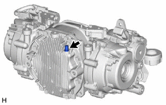
INSTALL TEMPERATURE SENSOR (for LH Side)
-
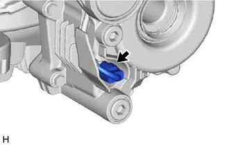
Using a 22 mm deep socket wrench, install a new gasket and temperature sensor.
- Torque:
- 39.2 N*m { 400 kgf*cm, 29 ft.*lbf }
-
-
INSTALL TEMPERATURE SENSOR (for RH Side)
Tech Tips
Use the same procedure as for the LH side.
-
INSTALL TORQUE TRANSFER MODULE MOTOR SUB-ASSEMBLY (for LH Side)
-
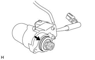

ATF WS Apply ATF WS to a new O-ring and install the O-ring to the torque transfer module motor sub-assembly.
-
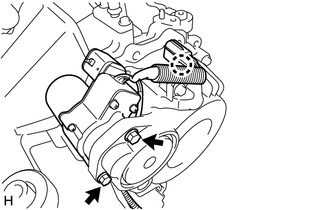
Install the torque transfer module motor sub-assembly with the 2 bolts.
- Torque:
- 12 N*m { 122 kgf*cm, 9 ft.*lbf }
Note
Make sure that the wire harness for the temperature sensor passes through the clearance between the torque transfer module motor sub-assembly and torque transfer module and is not pinched or pulled.
-
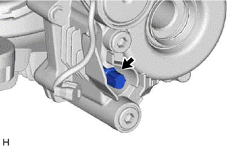
Engage the claw to install the connector.
-
Connect the connector.
-
-
INSTALL TORQUE TRANSFER MODULE MOTOR SUB-ASSEMBLY (for RH Side)
Tech Tips
Use the same procedure as for the LH side.
-
INSTALL REAR DRIVE SHAFT OIL SEAL LH
-
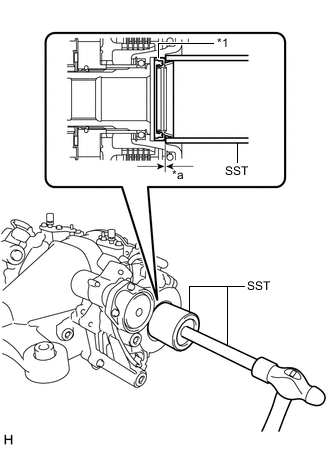
*1 Rear Drive Shaft Oil Seal LH *a Oil Seal Installation Depth Using SST and a hammer, install a new rear drive shaft oil seal LH.
- SST
- 09649-17010
- 09950-70010 ( 09951-07150 )
Oil Seal Installation Depth -0.5 to 0.5 mm (-0.0197 to 0.0196 in.) Note
-
Make sure to check the identification marks on the rear drive shaft oil seal LH before installation because the part numbers differ between the left and right sides.
-
To ensure a proper seal, evenly tap in the rear drive shaft oil seal LH.
-
When installing the rear drive shaft oil seal LH, tap it in until the outer surface is flush with the torque transfer module.
-
Make sure the difference between the maximum and minimum measured values of the oil seal installation depth is less than 0.58 mm (0.0228 in.), as a greater difference may lead to fluid leaks.
-
-
INSTALL REAR DRIVE SHAFT OIL SEAL RH
Tech Tips
Use the same procedure as for the LH side.
-
INSTALL REAR DIFFERENTIAL CARRIER COVER
-
Remove any old seal packing from the rear differential carrier and rear differential carrier cover using a scraper and wire brush. Then remove the oil with non-residue solvent or equivalent.
Note
Do not damage the contact surface.
-
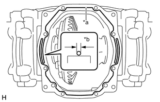
*a Seal Packing *b 2 to 3 mm (0.0787 to 0.118 in.) Apply seal packing to the rear differential carrier as shown in the illustration.
Seal Packing Toyota Genuine Seal Packing 1281, Three bond 1281 or equivalent Tech Tips
-
Apply seal packing in a continuous bead 2 to 3 mm (0.0787 to 0.118 in.) in diameter.
-
Stop applying seal packing after allowing it to overlap with the beginning of the bead by at least 10 mm (0.394 in.).
-
Install the rear differential carrier cover within 3 minutes of applying seal packing. If the rear differential carrier cover is not installed within 3 minutes of applying seal packing, completely remove and then reapply seal packing.
-
After installing the rear differential carrier cover, do not add oil within 1 hour or allow rapid acceleration or deceleration within 12 hours.
-
-
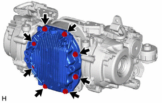
Install the rear differential carrier cover with the 8 bolts.
- Torque:
- 46.6 N*m { 475 kgf*cm, 34 ft.*lbf }
-
-
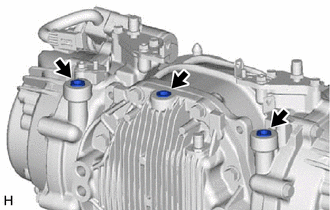
INSTALL REAR DIFFERENTIAL BREATHER PLUG
-
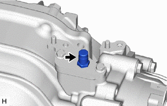
Install the rear differential breather plug to the rear differential carrier.
- Torque:
- 20.6 N*m { 210 kgf*cm, 15 ft.*lbf }
Tech Tips
Use the same procedure for the other side.
-
Install the rear differential breather plug to the rear differential carrier cover.
- Torque:
- 20.6 N*m { 210 kgf*cm, 15 ft.*lbf }
-
-
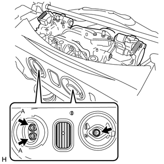
INSTALL REAR DIFFERENTIAL FILLER PLUG (for Upper Side)
-
Using an 8 mm hexagon socket wrench, install 3 new rear differential filler plugs to the torque vectoring differential FDU (Final Drive Unit).
- Torque:
- 30 N*m { 306 kgf*cm, 22 ft.*lbf }
Note
When using a new torque vectoring differential FDU (Final Drive Unit) or rear differential carrier cover, use new rear differential filler plugs.
-
-
INSTALL TORQUE VECTORING DIFFERENTIAL FDU (FINAL DRIVE UNIT)
Note
-
Do not damage the installation surface when installing the torque vectoring differential FDU (Final Drive Unit).
-
The remaining oil may leak out when installing the torque vectoring differential FDU (Final Drive Unit).
-
Securely support the torque vectoring differential FDU (Final Drive Unit) while performing this step to avoid excessively tilting or dropping the torque vectoring differential FDU (Final Drive Unit).
-
Install the bolts with the torque vectoring differential FDU (Final Drive Unit) secured.
Tech Tips
As there are 2 types of bolts (front side), the same type bolt must be used during removal and installation.
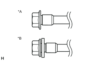
*A Bolt Type A *B Bolt Type B
-
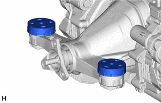
Install the 2 rear upper differential mount stoppers.
-
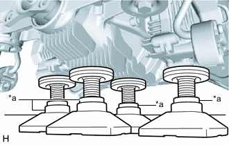
*a Attachment Support the torque vectoring differential FDU (Final Drive Unit) with 4 attachments or equivalent tools as shown in the illustration.
CAUTION:
The torque vectoring differential FDU (Final Drive Unit) is a heavy component. Make sure that it is supported securely.
Note
Use attachments or equivalent tools to keep the torque vectoring differential FDU (Final Drive Unit) level.
-
Temporarily install the rear suspension member sub-assembly to the torque vectoring differential FDU (Final Drive Unit).
-
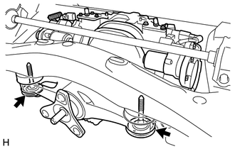
Temporarily install the torque vectoring differential FDU (Final Drive Unit) to the rear suspension member sub-assembly with the 2 rear lower differential mount stoppers and 2 new bolts.
-
Using a 12 mm hexagon socket wrench, temporarily install the torque vectoring differential FDU (Final Drive Unit) to the rear suspension member sub-assembly with 3 new bolts.
Tech Tips
Before installing the bolts, make sure that there is no clearance between the torque vectoring differential FDU (Final Drive Unit) and rear differential mount cushion.
-
Using a 12 mm hexagon socket wrench, tighten the 3 bolts.
- Torque:
- 103 N*m { 1050 kgf*cm, 76 ft.*lbf }
Note
Do not tilt the sleeve or deform the rubber of the rear differential mount cushion when tightening the bolt.
Tech Tips
Tighten the 2 bolts (A) first.
-
Tighten the 2 bolts.
- Torque:
- Bolt Type A
- 95.1 N*m { 970 kgf*cm, 70 ft.*lbf }
- Bolt Type B
- 88.9 N*m { 907 kgf*cm, 66 ft.*lbf }
-
-
INSTALL REAR SUSPENSION ARM BRACKET ASSEMBLY
-
INSTALL NO. 4 FLOOR WIRE
-
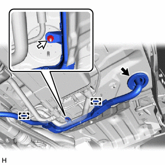
Insert the 4 pins to temporarily install the No. 4 floor wire.
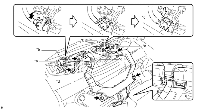
*a Connector (A) *b Connector (B) *c Lock *d Pin *e Clamp - - -
Engage the 2 clamps.
-
Connect the 2 connectors (A).
-
Connect the 2 connectors (B) as shown in the illustration to connect the No. 4 floor wire.
Tech Tips
When connecting the connector with lock lever, return the lock lever to its original position to engage the claw and securely push in the lock of the lock lever to connect the connector as shown in the illustration.
-
Install the 6 bolts.
- Torque:
- 13 N*m { 133 kgf*cm, 10 ft.*lbf }
-
-
INSTALL REAR SUSPENSION MEMBER SUB-ASSEMBLY
-
CONNECT NO. 4 FLOOR WIRE
-
Pass the No. 4 floor wire through the grommet hole to the inside of the vehicle.
-
Grommet 
Nut Install the nut.
- Torque:
- 5.4 N*m { 55 kgf*cm, 48 in.*lbf }
-
Engage the 2 clamps.
-
Engage the grommet to connect the No. 4 floor wire.
-
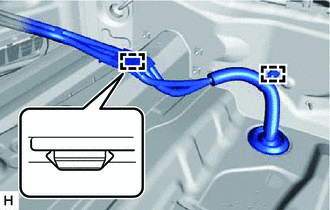
Engage the 2 clamps.
-
Connect the 2 connectors (B) as shown in the illustration to connect the No. 4 floor wire.
Tech Tips
When connecting the connector with lock lever, return the lock lever to its original position to engage the claw and securely push in the lock of the lock lever to connect the connector as shown in the illustration.
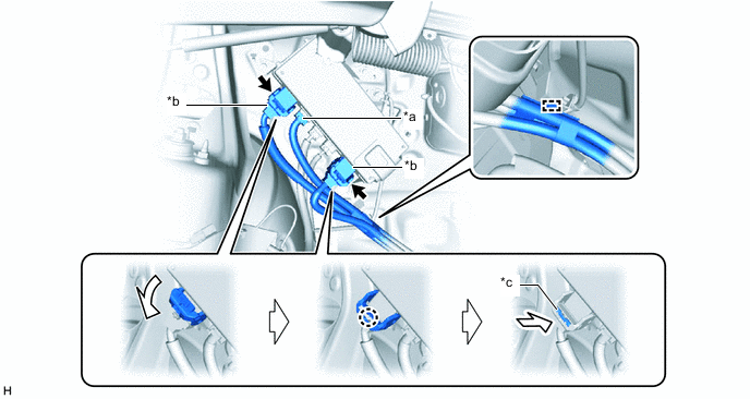
*a Connector (A) *b Connector (B) *c Lock - - -
Connect the connector (A).
-
Engage the clamp.
-
-
INSTALL NO. 1 FLOOR UNDER COVER ASSEMBLY
-
INSTALL LUGGAGE COMPARTMENT TRIM COVER RH
-
INSTALL FRONT LUGGAGE COMPARTMENT TRIM COVER
-
INSTALL FRONT UPPER LUGGAGE COMPARTMENT TRIM COVER
-
INSTALL NO. 1 LUGGAGE COMPARTMENT LIGHT ASSEMBLY
-
INSTALL REAR LUGGAGE COMPARTMENT TRIM COVER
-
INSTALL SPARE WHEEL COVER TRAY (w/o Spare Tire)
-
INSTALL NO. 1 LUGGAGE COMPARTMENT TRIM COVER
-
ADD DIFFERENTIAL OIL
-
ADD TORQUE TRANSFER MODULE FLUID
-
INSPECT FOR TORQUE TRANSFER MODULE FLUID AND DIFFERENTIAL OIL LEAK
-
CONNECT CABLE TO NEGATIVE BATTERY TERMINAL
Note
When disconnecting the cable, some systems need to be initialized after the cable is reconnected.
-
TORQUE VECTORING DIFFERENTIAL SYSTEM CALIBRATION
-
When the torque transfer module motor sub-assembly is removed/installed, or the torque vectoring differential FDU (Final Drive Unit) is replaced, Learning Value Initialization must be performed.
-