REAR DIFFERENTIAL CARRIER ASSEMBLY(for LSD) REASSEMBLY

PROCEDURE
-
INSTALL DIFFERENTIAL RING GEAR
-
Clean the contact surfaces of the rear differential case sub-assembly and differential ring gear.
-
Clean the ring gear set bolt hole.
-
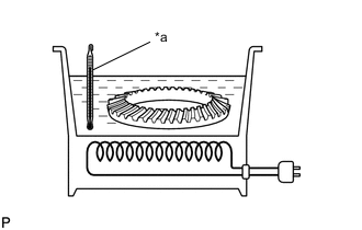
*a 100°C (212°F) Heat the differential ring gear to approximately 100°C (212°F) in boiling water.
-
Carefully take the differential ring gear out of the boiling water.
CAUTION:
Use thick gloves to protect your hands as the differential ring gear is hot.
-
Secure the rear differential case sub-assembly between aluminum plates in a vise.
Note
Do not overtighten the vise.
-
After the moisture on the differential ring gear has completely evaporated, quickly install the differential ring gear to the rear differential case sub-assembly.
-
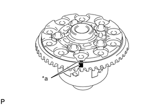
*a Matchmark Align the matchmarks on the differential ring gear and rear differential case sub-assembly.
-
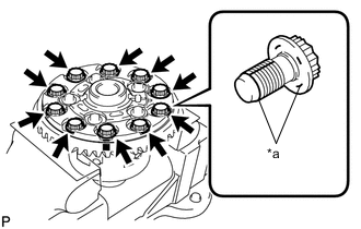
*a Thread Lock After the differential ring gear has cooled sufficiently, install 10 new rear differential case bolts to which thread lock has been applied.
Adhesive Toyota Genuine Adhesive 1360K, Three Bond 1360K or equivalent. Note
-
New rear differential case bolts should be used every time the differential ring gear is installed.
-
Do not allow oil to adhere to the rear differential case bolts during installation.
-
-
Temporarily install the 10 rear differential case bolts.
-
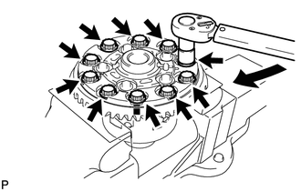
After the differential ring gear cools down, tighten the 10 rear differential case bolts.
- Torque:
- 63.7 N*m { 650 kgf*cm, 47 ft.*lbf }
Note
Tighten diametrically opposite rear differential case bolts in pairs.
-
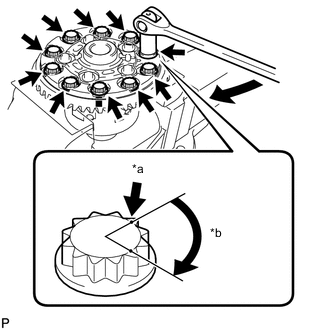
*a Paint Mark *b 60° to 90° Tighten the 10 rear differential case bolts an additional 60° to 90°.
Note
Tighten diametrically opposite rear differential case bolts in pairs.
-
-
INSTALL REAR DIFFERENTIAL CASE BEARING
-
Using SST and a press, install the 2 rear differential case bearing inner races to the rear differential case sub-assembly.
- SST
- 09950-60010 ( 09951-00560, 09951-00570 )
- 09950-70010 ( 09951-07100 )
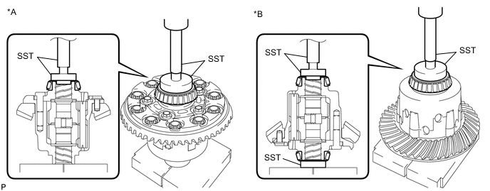
*A for LH Side *B for RH Side Note
-
New bearings are coated with anti-rust oil. If using new bearings, do not wash it off.
-
Do not apply Toyota genuine differential gear oil LX 75W-85 GL-5 or equivalent to a new bearing.
-
Do not deform the bearing cage. Set SST to the center of the rear differential case sub-assembly.
-
If the bearing is replaced, replace it and its outer race as a set.
-
-
INSTALL REAR DRIVE PINION REAR TAPERED ROLLER BEARING
-
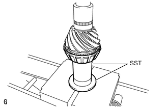
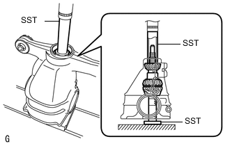
Using SST and a press, install the rear drive pinion rear tapered roller bearing inner race to the differential drive pinion.
- SST
- 09316-60011 ( 09316-00031 )
- 09612-24014 ( 09613-22011 )
Note
-
New bearings are coated with anti-rust oil. If using new bearings, do not wash it off.
-
Do not apply Toyota genuine differential gear oil LX 75W-85 GL-5 or equivalent to a new bearing.
Tech Tips
Disassemble SST (09613-22011) and use only the pipe section.
-
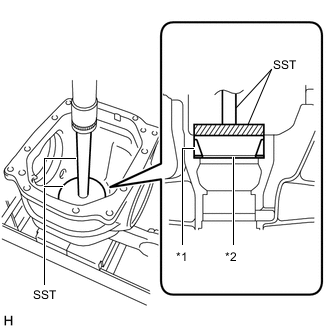
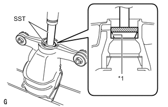
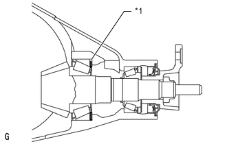
*1 Rear Drive Pinion Rear Tapered Roller Bearing Outer Race *2 Rear Differential Drive Pinion Plate Washer Using SST and a press, install a new rear differential drive pinion plate washer and rear drive pinion rear tapered roller bearing outer race.
- SST
- 09255-10012
- 09950-70010 ( 09951-07200 )
Note
-
New bearings are coated with anti-rust oil. If using new bearings, do not wash it off.
-
Do not apply Toyota genuine differential gear oil LX 75W-85 GL-5 or equivalent to a new bearing.
Tech Tips
Select a rear differential drive pinion plate washer of the same thickness as the removed one.
-
-
INSTALL REAR DRIVE PINION FRONT TAPERED ROLLER BEARING
-
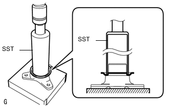
*1 Rear Drive Pinion Front Tapered Roller Bearing Outer Race Using SST and a press, install the rear drive pinion front tapered roller bearing outer race.
- SST
- 09950-60020 ( 09951-00710 )
- 09950-70010 ( 09951-07100 )
Note
-
New bearings are coated with anti-rust oil. If using new bearings, do not wash it off.
-
Do not apply Toyota genuine differential gear oil LX 75W-85 GL-5 or equivalent to a new bearing.
-
Install the rear drive pinion front tapered roller bearing inner race to the rear differential carrier.
Note
-
New bearings are coated with anti-rust oil. If using new bearings, do not wash it off.
-
Do not apply Toyota genuine differential gear oil LX 75W-85 GL-5 or equivalent to a new bearing.
-
-
-
INSTALL REAR DIFFERENTIAL DUST DEFLECTOR
Tech Tips
Perform this procedure only when replacing the rear differential dust deflector.
-
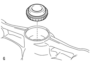
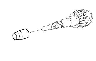
Using SST and a press, install a new rear differential dust deflector to the rear drive pinion companion flange.
- SST
- 09316-60011 ( 09316-00011 )
Note
-
Slowly press in the rear differential dust deflector.
-
Do not excessively press in the rear differential dust deflector.
-
If any burrs remain after pressing in the rear differential dust deflector, remove them.
-
-
INSTALL DIFFERENTIAL DRIVE PINION
-
Using SST and a press, install the differential drive pinion.
- SST
- 09316-60011 ( 09316-00011, 09316-00041 )
- 09608-04031
Tech Tips
Install the rear differential drive pinion bearing spacer and rear differential carrier oil seal after adjusting the tooth contact pattern.
-
-
INSTALL REAR DIFFERENTIAL DRIVE PINION OIL SLINGER
-
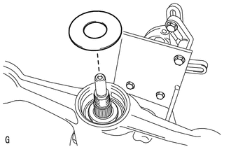
Install the rear differential drive pinion oil slinger.
-
-
INSTALL REAR DRIVE PINION COMPANION FLANGE
-
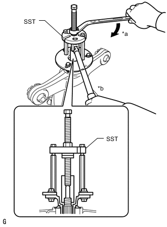
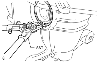
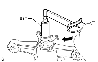
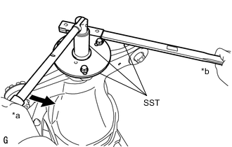
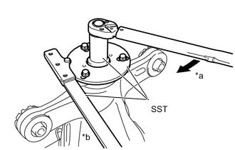
*a Turn *b Hold Using SST, install the rear drive pinion companion flange.
- SST
- 09950-30012 ( 09951-03010, 09953-03010, 09954-03010, 09955-03040, 09956-03060 )
Note
-
Install the rear drive pinion companion flange so that there is a slight looseness in the differential drive pinion because the rear differential drive pinion bearing spacer is not yet installed.
-
Apply molybdenum grease to the threads of SST center bolt (09953-03010) before use.
Tech Tips
When securing SST and the rear drive pinion companion flange, it is recommended to use M8 X P 1.25 bolts with a length of approximately 40 mm.
-
Apply hypoid gear oil LSD to the threads of a new rear drive pinion nut and the differential drive pinion.
-
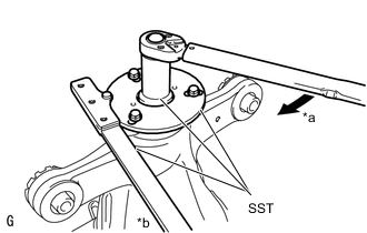
*a Turn *b Hold Using SST and a torque wrench, hold the rear drive pinion companion flange and temporarily tighten the rear drive pinion nut.
- SST
- 09229-55010
- 09330-00021
- 09950-30012 ( 09955-03040 )
- Torque:
- 100 N*m { 1020 kgf*cm, 74 ft.*lbf }
CAUTION:
Hold the overhaul stand during the operation.
Tech Tips
-
When securing SST and the rear drive pinion companion flange, it is recommended to use M8 X P 1.25 bolts with a length of approximately 40 mm.
-
Tighten the rear drive pinion nut approximately 100 N*m (1020 kgf*cm, 74 ft.*lbf), and tighten it further while checking the preload.
-
-
ADJUST DIFFERENTIAL DRIVE PINION PRELOAD
-
Turn the bearing clockwise and counterclockwise several times to stabilize it.
-
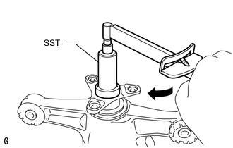
Using SST and a torque wrench, measure the differential drive pinion preload within the differential ring gear backlash.
- SST
- 09229-55010
Standard Drive Pinion Preload (Starting Torque) 1.15 to 1.55 N*m (12 to 15 kgf*cm, 11 to 13 in.*lbf) Note
-
As there is no rear differential drive pinion bearing spacer, tighten the rear drive pinion nut in several steps.
-
Do not overtighten the rear drive pinion nut.
If the preload is less than the specified minimum value, check the preload while retightening the rear drive pinion nut by 5 to 10° to adjust it into the specified range.
Torque 490 N*m (4997 kgf*cm, 361 ft.*lbf) or less
-
-
INSTALL REAR DIFFERENTIAL CASE SUB-ASSEMBLY
-
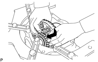
Insert the rear differential case sub-assembly from the differential ring gear tooth side to install the rear differential case sub-assembly as shown in the illustration.
Note
Do not damage the rear differential case bearing and differential ring gear.
-
-
INSTALL REAR DIFFERENTIAL CASE BEARING
-
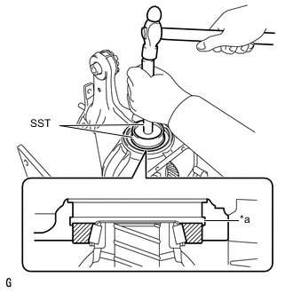
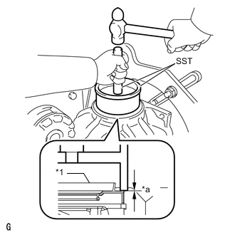
*a Groove Using SST and a hammer, install the rear differential case bearing outer race RH to the differential ring gear tooth side.
- SST
- 09608-32010
- 09950-70010 ( 09951-07200 )
Note
-
New bearings are coated with anti-rust oil. If using new bearings, do not wash it off.
-
Do not apply Toyota genuine differential gear oil LX 75W-85 GL-5 or equivalent to a new bearing.
Tech Tips
Tap in the rear differential case bearing outer race RH until half of the rear differential side gear shaft snap ring groove of the rear differential carrier can be seen.
-
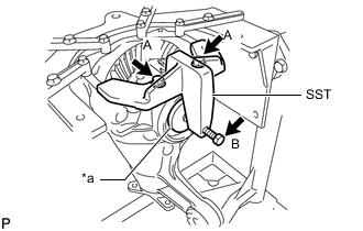
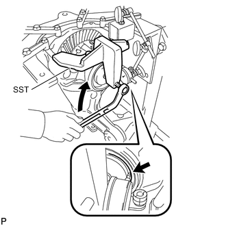
*a Disc Install SST to the rear differential carrier with the 2 bolts (A).
- SST
- 09571-50010
-
Tighten the SST bolt (B) until the SST disc lightly touches the rear differential case bearing outer race RH.
-
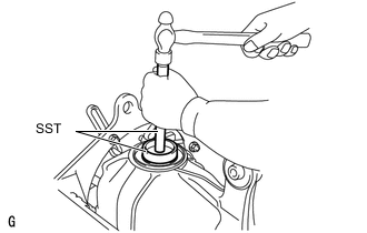
Using SST and a hammer, install the rear differential case bearing outer race LH to the differential ring gear back surface side.
- SST
- 09608-32010
- 09950-70010 ( 09951-07200 )
Note
-
New bearings are coated with anti-rust oil. If using new bearings, do not wash it off.
-
Do not apply Toyota genuine differential gear oil LX 75W-85 GL-5 or equivalent to a new bearing.
Tech Tips
Tap in the rear differential case bearing outer race LH until it touches the rear differential case bearing inner race roller.
-
-
INSTALL REAR DIFFERENTIAL SIDE GEAR SHAFT SNAP RING
-
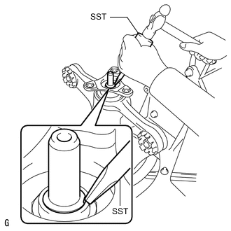
Using SST, install the thinnest rear differential side gear shaft snap ring to the rear differential carrier on the differential ring gear back surface side.
- SST
- 09905-00031
Tech Tips
-
If the final gear set (differential drive pinion and differential ring gear) and rear differential case bearing are new, select a thinner rear differential side gear shaft snap ring and install it.
-
If the final gear set (differential drive pinion and differential ring gear) and rear differential case bearing are reused, install a rear differential side gear shaft snap ring with the same thickness as the removed one.
-
Install a dial indicator to the rear differential carrier.
-
Tighten the SST bolt to alter the shape of the rear differential carrier by approximately 0.1 mm (0.00394 in.).
- SST
- 09571-50010
Note
Observe the dial indicator to ensure that the shape of the rear differential carrier does not change by more than 0.2 mm (0.00787 in.).
Tech Tips
Tighten the SST bolt to apply the preload to the rear differential case bearing.
-
Turn the differential ring gear clockwise and counterclockwise several times.
-
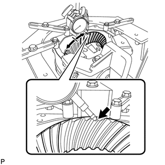
Using a dial indicator, measure the ring gear backlash of the differential ring gear at 3 positions.
Standard Backlash 0.08 to 0.13 mm (0.00315 to 0.00511 in.) Note
The difference between the maximum and minimum values must be within 0.05 mm (0.00197 in.).
Tech Tips
-
Record the measured ring gear backlash to use as a reference for selecting a rear differential side gear shaft snap ring.
-
If the ring gear backlash is not within the specified range, replace the rear differential side gear shaft snap ring on the differential ring gear tooth side with a rear differential side gear shaft snap ring of a different thickness as described in the following procedure.
-
Inspect the tooth contact and use the result as a reference for selecting a rear differential side gear shaft snap ring.
-
-
Loosen the SST bolt and separate the SST disc from the rear differential case bearing outer race RH.
Note
Do not remove SST.
-
Using SST and a hammer, create a clearance between the rear differential side gear shaft snap ring on the differential ring gear back surface side and the rear differential case bearing outer race LH.
- SST
- 09608-32010
- 09950-70010 ( 09951-07200 )
-

Using SST, remove the rear differential side gear shaft snap ring from the differential ring gear back surface side.
- SST
- 09905-00031
-
Using SST, install a rear differential side gear shaft snap ring with a different thickness.
- SST
- 09905-00031
Tech Tips
When the rear differential side gear shaft snap ring thickness changes by 0.02 mm (0.000787 in.), the ring gear backlash also changes by 0.02 mm (0.000787 in.).
Rear Differential Side Gear Shaft Snap Ring Thickness Part No. No. Thickness Part No. No. Thickness 90521-99062 66 3.6475 to 3.6725 mm (0.14360 to 0.14459 in.) 90521-99084 06 4.0475 to 4.0725 mm (0.15935 to 0.16033 in.) 90521-99063 68 3.6675 to 3.6925 mm (0.14439 to 0.14537 in.) 90521-99085 08 4.0675 to 4.0925 mm (0.16014 to 0.16112 in.) 90521-99064 70 3.6875 to 3.7125 mm (0.14518 to 0.14616 in.) 90521-99086 10 4.0875 to 4.1125 mm (0.16092 to 0.16191 in.) 90521-99065 72 3.7075 to 3.7325 mm (0.14596 to 0.14695 in.) 90521-99087 12 4.1075 to 4.1325 mm (0.16171 to 0.16270 in.) 90521-99066 74 3.7275 to 3.7525 mm (0.14675 to 0.14774 in.) 90521-99088 14 4.1275 to 4.1525 mm (0.16250 to 0.16348 in.) 90521-99067 76 3.7475 to 3.7725 mm (0.14754 to 0.14852 in.) 90521-99089 16 4.1475 to 4.1725 mm (0.16329 to 0.16427 in.) 90521-99068 78 3.7675 to 3.7925 mm (0.14833 to 0.14931 in.) 90521-99090 18 4.1675 to 4.1925 mm (0.16407 to 0.16506 in.) 90521-99070 80 3.7875 to 3.8125 mm (0.14911 to 0.15010 in.) 90521-99091 20 4.1875 to 4.2125 mm (0.16486 to 0.16585 in.) 90521-99071 82 3.8075 to 3.8325 mm (0.14990 to 0.15089 in.) 90521-99092 22 4.2075 to 4.2325 mm (0.16565 to 0.16663 in.) 90521-99072 84 3.8275 to 3.8525 mm (0.15069 to 0.15167 in.) 90521-99095 24 4.2275 to 4.2525 mm (0.16644 to 0.16742 in.) 90521-99073 86 3.8475 to 3.8725 mm (0.15148 to 0.15246 in.) 90521-99096 26 4.2475 to 4.2725 mm (0.16722 to 0.16821 in.) 90521-99074 88 3.8675 to 3.8925 mm (0.15226 to 0.15325 in.) 90521-99097 28 4.2675 to 4.2925 mm (0.16801 to 0.16900 in.) 90521-99075 90 3.8875 to 3.9125 mm (0.15305 to 0.15404 in.) 90521-99100 30 4.2875 to 4.3125 mm (0.16880 to 0.16978 in.) 90521-99076 92 3.9075 to 3.9325 mm (0.15384 to 0.15482 in.) 90521-99101 32 4.3075 to 4.3325 mm (0.16959 to 0.17057 in.) 90521-99077 94 3.9275 to 3.9525 mm (0.15463 to 0.15561 in.) 90521-99102 34 4.3275 to 4.3525 mm (0.17037 to 0.17136 in.) 90521-99078 96 3.9475 to 3.9725 mm (0.15541 to 0.15640 in.) 90521-99103 36 4.3475 to 4.3725 mm (0.17116 to 0.17215 in.) 90521-99079 98 3.9675 to 3.9925 mm (0.15620 to 0.15718 in.) 90521-99104 38 4.3675 to 4.3925 mm (0.17195 to 0.17293 in.) 90521-99081 00 3.9875 to 4.0125 mm (0.15699 to 0.15797 in.) 90521-99105 40 4.3875 to 4.4125 mm (0.17274 to 0.17372 in.) 90521-99082 02 4.0075 to 4.0325 mm (0.15778 to 0.15876 in.) 90521-99107 42 4.4075 to 4.4325 mm (0.17352 to 0.17451 in.) 90521-99083 04 4.0275 to 4.0525 mm (0.15856 to 0.15955 in.) - - - -
Using a plastic hammer, lightly tap the differential ring gear tooth side of the rear differential carrier.
-
Install a dial indicator to the rear differential carrier.
-
Tighten the SST bolt to alter the shape of the rear differential carrier by approximately 0.1 mm (0.00394 in.).
- SST
- 09571-50010
Note
Observe the dial indicator to ensure that the shape of the rear differential carrier does not change by more than 0.2 mm (0.00787 in.).
-
Using a dial indicator, measure the ring gear backlash of the differential ring gear at 3 positions.
Standard Backlash 0.08 to 0.13 mm (0.00315 to 0.00511 in.) Tech Tips
-
Record the measured ring gear backlash to use as a reference for selecting a rear differential side gear shaft snap ring.
-
Inspect the tooth contact and use the result as a reference for selecting a rear differential side gear shaft snap ring.
If the ring gear backlash is not within the specified range, replace the rear differential side gear shaft snap ring on the back surface of the differential ring gear with one of a different thickness.
-
-
-
ADJUST DIFFERENTIAL RING GEAR BACKLASH
-
Install a dial indicator to the rear differential carrier.
-
Tighten the SST bolt to alter the shape of the rear differential carrier by approximately 0.1 mm (0.00394 in.).
- SST
- 09571-50010
Note
Observe the dial indicator to ensure that the shape of the rear differential carrier does not change by more than 0.2 mm (0.00787 in.).
-
Using SST, install the thinnest rear differential side gear shaft snap ring to the differential ring gear tooth side.
- SST
- 09905-00031
-
Remove the dial indicator and loosen the bolt until the SST disc is separated from the rear differential case bearing outer race RH on the differential ring gear tooth side.
-
Using a plastic hammer, lightly tap the differential ring gear tooth side of the rear differential carrier to stabilize the rear differential case bearing.
-
Using a dial indicator, measure the ring gear backlash of the differential ring gear at 3 positions. If even one ring gear backlash reading is smaller than the specified value, adjust the differential ring gear backlash by replacing the rear differential side gear shaft snap ring on the differential ring gear tooth side with a thicker one.
Standard Backlash 0.08 to 0.13 mm (0.00315 to 0.00511 in.) If the value is not within the specified range, replace the rear differential side gear shaft snap ring with one of a different thickness in the following procedure.
-
Remove the 2 bolts and SST.
-
-
ADJUST TOTAL PRELOAD
-
Turn the bearing clockwise and counterclockwise several times to stabilize it.
-
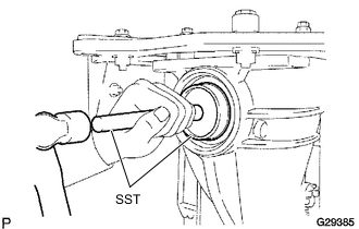
Using SST and a torque wrench, measure the preload with the teeth of the differential drive pinion and differential ring gear in contact.
- SST
- 09229-55010
Total preload (at starting) New bearing 1.81 to 3.41 N*m (19 to 34 kgf*cm, 17 to 30 in.*lbf) Reused bearing 1.64 to 2.86 N*m (17 to 29 kgf*cm, 15 to 25 in.*lbf) Note
-
If the measured preload is less than the specified value, replace the rear differential side gear shaft snap ring of the differential ring gear tooth surface side with a thicker one.
-
If the measured preload is more than the specified value, replace the rear differential side gear shaft snap ring of the differential ring gear tooth surface side with a thinner one.
Tech Tips
When the rear differential side gear shaft snap ring thickness changes by 0.02 mm (0.000787 in.), the total preload will change by approximately 0.1 N*m (1 kgf*cm, 1 in.*lbf).
-
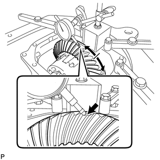
Set a dial indicator to the end of the differential ring gear face.
-
While holding the rear drive pinion companion flange, rotate the differential ring gear and measure the ring gear backlash.
Standard Backlash 0.08 to 0.13 mm (0.00315 to 0.00511 in.) Tech Tips
-
If the measured value is out of the specified range, adjust it by increasing or decreasing the thickness of both the right and left rear differential side gear shaft snap rings equally.
-
When the rear differential side gear shaft snap ring thickness changes by 0.02 mm (0.000787 in.), the ring gear backlash also changes by 0.02 mm (0.000787 in.).
-
-
Recheck the total preload.
-
-
INSPECT TOOTH CONTACT BETWEEN RING GEAR AND DRIVE PINION
-
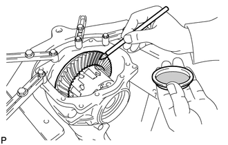
Coat 3 or 4 teeth at 3 different positions on the differential ring gear with Prussian blue.
-
Rotate the differential ring gear in both directions.
-
Inspect the tooth contact pattern.
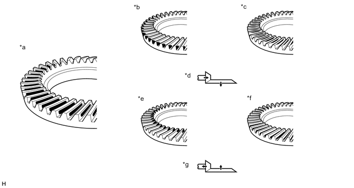
*a Proper Contact *b Heel Contact *c Face Contact *d Select an adjusting washer that will bring the drive pinion closer to the ring gear (*b, *c) *e Toe Contact *f Flank Contact *g Select an adjusting washer that will bring the drive pinion away from the ring gear (*e, *f) - - Note
Check the tooth contact pattern at 4 or more positions around circumference of the differential ring gear.
-
*1 Rear Differential Drive Pinion Plate Washer If the teeth are not contacting properly, use the following table to select a proper rear differential drive pinion plate washer for correction.
Tech Tips
-
If the contact pattern is face contact or flank contact, tooth contact may be adjustable while keeping the backlash within the specified range.
-
If the thickness of the rear differential drive pinion plate washer has been changed, adjust the ring gear backlash and measure the total preload.
Rear Differential Drive Pinion Plate Washer Thickness Part No. No. Thickness Part No. No. Thickness 90201-70002 88 1.87 to 1.89 mm (0.0737 to 0.0744 in.) 90201-70024 10 2.09 to 2.11 mm (0.0823 to 0.0830 in.) 90201-70004 90 1.89 to 1.91 mm (0.0745 to 0.0752 in.) 90201-70026 12 2.11 to 2.13 mm (0.0831 to 0.0838 in.) 90201-70006 92 1.91 to 1.93 mm (0.0752 to 0.0759 in.) 90201-70028 14 2.13 to 2.15 mm (0.0839 to 0.0846 in.) 90201-70008 94 1.93 to 1.95 mm (0.0760 to 0.0767 in.) 90201-70030 16 2.15 to 2.17 mm (0.0847 to 0.0854 in.) 90201-70010 96 1.95 to 1.97 mm (0.0768 to 0.0775 in.) 90201-70032 18 2.17 to 2.19 mm (0.0855 to 0.0862 in.) 90201-70012 98 1.97 to 1.99 mm (0.0776 to 0.0783 in.) 90201-70034 20 2.19 to 2.21 mm (0.0863 to 0.0870 in.) 90201-70014 00 1.99 to 2.01 mm (0.0784 to 0.0791 in.) 90201-70036 22 2.21 to 2.23 mm (0.0871 to 0.0878 in.) 90201-70016 02 2.01 to 2.03 mm (0.0792 to 0.0799 in.) 90201-70038 24 2.23 to 2.25 mm (0.0878 to 0.0885 in.) 90201-70018 04 2.03 to 2.05 mm (0.0800 to 0.0807 in.) 90201-70040 26 2.25 to 2.27 mm (0.0886 to 0.0893 in.) 90201-70020 06 2.05 to 2.07 mm (0.0808 to 0.0815 in.) 90201-70042 28 2.27 to 2.29 mm (0.0894 to 0.0901 in.) 90201-70022 08 2.07 to 2.09 mm (0.0815 to 0.0822 in.) - - - -
-
-
REMOVE REAR DIFFERENTIAL SIDE GEAR SHAFT SNAP RING (for RH Side)
-
REMOVE REAR DIFFERENTIAL SIDE GEAR SHAFT SNAP RING (for LH Side)
-
REMOVE REAR DIFFERENTIAL CASE BEARING (for LH Side)
-
REMOVE REAR DIFFERENTIAL CASE BEARING (for RH Side)
-
REMOVE REAR DIFFERENTIAL CASE SUB-ASSEMBLY
-
REMOVE REAR DRIVE PINION NUT
-
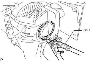
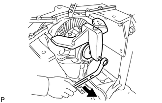
*a Turn *b Hold Using SST to hold the rear drive pinion companion flange, remove the rear drive pinion nut.
- SST
- 09229-55010
- 09330-00021
- 09950-30012 ( 09955-03040 )
CAUTION:
Hold the overhaul stand during the operation.
Tech Tips
When securing SST and the rear drive pinion companion flange, it is recommended to use M8 X P 1.25 bolts with a length of approximately 40 mm.
-
-
REMOVE REAR DRIVE PINION COMPANION FLANGE
-
REMOVE REAR DIFFERENTIAL DRIVE PINION OIL SLINGER
-
REMOVE DIFFERENTIAL DRIVE PINION
-
REMOVE REAR DRIVE PINION FRONT TAPERED ROLLER BEARING
-
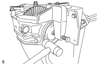
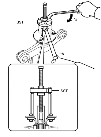
Remove the rear drive pinion front tapered roller bearing inner race from the rear differential carrier.
-
-
INSTALL REAR DIFFERENTIAL DRIVE PINION BEARING SPACER
-
Install a new rear differential drive pinion bearing spacer to the differential drive pinion.
Note
Install the rear differential drive pinion bearing spacer with the larger diameter side facing toward the differential drive pinion.
-
-
INSTALL REAR DRIVE PINION FRONT TAPERED ROLLER BEARING
-
Install the rear drive pinion front tapered roller bearing inner race to the rear differential carrier.
-
-
INSTALL DIFFERENTIAL DRIVE PINION
-

Using SST and a press, install the differential drive pinion to the rear differential carrier.
- SST
- 09316-60011 ( 09316-00011, 09316-00041 )
- 09608-04031
-
-
INSTALL REAR DIFFERENTIAL DRIVE PINION OIL SLINGER
-
Install the rear differential drive pinion oil slinger.
-
-
INSTALL REAR DIFFERENTIAL CARRIER OIL SEAL
-
INSTALL REAR DRIVE PINION COMPANION FLANGE
-
*a Turn *b Hold Using SST, install the rear drive pinion companion flange to the differential drive pinion.
- SST
- 09950-30012 ( 09951-03010, 09953-03010, 09954-03010, 09955-03040, 09956-03060 )
Note
Apply molybdenum grease to the threads of SST center bolt (09953-03010) before use.
Tech Tips
When securing SST and the rear drive pinion companion flange, it is recommended to use M8 X P 1.25 bolts with a length of approximately 40 mm.
-
Apply hypoid gear oil LSD to the threads of the rear drive pinion nut and the differential drive pinion.
-
*a Turn *b Hold Using SST and a torque wrench, hold the rear drive pinion companion flange and temporarily tighten the rear drive pinion nut.
- SST
- 09229-55010
- 09330-00021
- 09950-30012 ( 09955-03040 )
- Torque:
- 100 N*m { 1020 kgf*cm, 74 ft.*lbf }
CAUTION:
Hold the overhaul stand during the operation.
Note
Do not tighten the rear drive pinion nut excessively, otherwise the threads will be damaged.
Tech Tips
Tighten the rear drive pinion nut to approximately 100 N*m (1020 kgf*cm, 74 ft.*lbf), and then tighten it further while observing the preload.
-
-
INSTALL REAR DIFFERENTIAL CASE SUB-ASSEMBLY
-
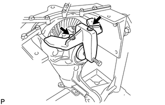
Insert the rear differential case sub-assembly from the differential ring gear tooth side to install the rear differential case sub-assembly as shown in the illustration.
Note
Do not damage the rear differential case bearing and differential ring gear.
-
-
INSTALL REAR DIFFERENTIAL CASE BEARING
-
*a Groove Using SST and a hammer, install the rear differential case bearing outer race RH to the differential ring gear tooth side.
- SST
- 09608-32010
- 09950-70010 ( 09951-07200 )
Tech Tips
Tap in the rear differential case bearing outer race RH until half of the rear differential side gear shaft snap ring groove of the rear differential carrier can be seen.
-
*a Disc Install SST to the rear differential carrier with the 2 bolts (A).
- SST
- 09571-50010
-
Tighten the SST bolt (B) until the SST disc lightly touches the rear differential case bearing outer race RH.
-
Using SST and a hammer, install the rear differential case bearing outer race LH to the differential ring gear back surface side.
- SST
- 09608-32010
- 09950-70010 ( 09951-07200 )
Tech Tips
Tap in the rear differential case bearing outer race LH until it touches the rear differential case bearing inner race roller.
-
-
INSTALL REAR DIFFERENTIAL SIDE GEAR SHAFT SNAP RING
-

Using SST, install the rear differential side gear shaft snap ring to the rear differential carrier on the differential ring gear back surface side.
- SST
- 09905-00031
Tech Tips
Use the rear differential side gear shaft snap ring installed when performing tooth contact adjustment.
-
Install a dial indicator to the rear differential carrier.
-
Tighten the SST bolt to alter the shape of the rear differential carrier by approximately 0.1 mm (0.00394 in.).
- SST
- 09571-50010
Note
Observe the dial indicator to ensure that the shape of the rear differential carrier does not change by more than 0.2 mm (0.00787 in.).
-
Using SST, install the rear differential side gear shaft snap ring to the differential ring gear tooth side.
- SST
- 09905-00031
Tech Tips
Use the rear differential side gear shaft snap ring installed when performing tooth contact adjustment.
-
Remove the dial indicator.
-
Using a plastic hammer, lightly tap the differential ring gear tooth side of the rear differential carrier to stabilize the rear differential case bearing.
-
Remove the 2 bolts and SST.
-
-
ADJUST DIFFERENTIAL DRIVE PINION PRELOAD
-
Turn the bearing clockwise and counterclockwise several times to stabilize it.
-
Using SST and a torque wrench, measure the differential drive pinion preload within the differential ring gear backlash.
- SST
- 09229-55010
Standard Drive Pinion Preload (Starting Torque) 1.25 to 1.65 N*m (13 to 16 kgf*cm, 12 to 14 in.*lbf)
-
If the preload is less than the specified minimum value, check the preload while retightening the rear drive pinion nut 5 to 10°.
Torque 490 N*m (4997 kgf*cm, 361 ft.*lbf) or less -
If the preload is less than the specified minimum value even when the tightening torque of the rear drive pinion nut is more than the specified maximum value, remove the rear drive pinion nut and check that the threads of the rear drive pinion nut and differential drive pinion are not damaged.
-
If the threads are not damaged, replace the rear differential drive pinion bearing spacer. Apply hypoid gear oil LSD to the threads of the differential drive pinion and repeat the procedure.
-
-
INSPECT TOTAL PRELOAD
-
Turn the bearing clockwise and counterclockwise several times to stabilize it.
-
Using SST and a torque wrench, measure the preload with the teeth of the differential drive pinion and differential ring gear in contact.
- SST
- 09229-55010
Standard Total Preload (Starting Torque) New bearing 1.91 to 3.51 N*m (20 to 35 kgf*cm, 17 to 31 in.*lbf) Reused bearing 1.74 to 2.96 N*m (18 to 30 kgf*cm, 16 to 26 in.*lbf) If the total preload is not within the specified range, adjust the total preload or repair as necessary.
-
-
INSPECT DIFFERENTIAL RING GEAR BACKLASH
-
While holding the rear drive pinion companion flange, rotate the differential ring gear and measure the ring gear backlash.
Standard Backlash 0.08 to 0.13 mm (0.00315 to 0.00511 in.) Tech Tips
Measure the backlash at more than 3 points on the circumference of the differential ring gear.
If the ring gear backlash is not within the specified range, adjust the ring gear backlash or repair as necessary.
-
-
INSPECT RUNOUT OF DIFFERENTIAL DRIVE PINION
-
*a 10 mm (0.394 in.) Using a dial indicator, measure the runout of the differential drive pinion at a position 10 mm (0.394 in.) away from the end of the differential drive pinion.
Maximum Runout 0.08 mm (0.00315 in.) If the runout is more than the maximum, replace the differential drive pinion and differential ring gear.
-
-
STAKE REAR DRIVE PINION NUT
-
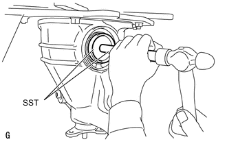
Using SST and a hammer, stake the rear drive pinion nut.
- SST
- 09930-00010
-
-
INSTALL REAR DRIVE SHAFT OIL SEAL
-
*1 Rear Drive Shaft Oil Seal *a Oil Seal Installation Depth Using SST and a hammer, install 2 new rear drive shaft oil seals.
- SST
- 09223-15030
- 09950-70010 ( 09951-07150 )
Oil Seal Installation Depth -0.5 to 0.5 mm (-0.0197 to 0.0196 in.) Note
-
Make sure to check the identification marks on the rear drive shaft oil seals before installation because the part numbers differ between the left and right sides.
-
To ensure a proper seal, evenly tap in the rear drive shaft oil seals.
-
When installing the rear drive shaft oil seals, tap them in until the outer surface of each seal is flush with the rear differential carrier.
-
Make sure the difference between the maximum and minimum measured values of the oil seal installation depth is less than 0.88 mm (0.0347 in.), as a greater difference may lead to oil leaks.
-
-
INSTALL REAR DIFFERENTIAL DRAIN PLUG
-
Using a 10 mm hexagon socket wrench, install a new gasket and the rear differential drain plug.
- Torque:
- 49 N*m { 500 kgf*cm, 36 ft.*lbf }
-
-
REMOVE REAR DIFFERENTIAL CARRIER
-
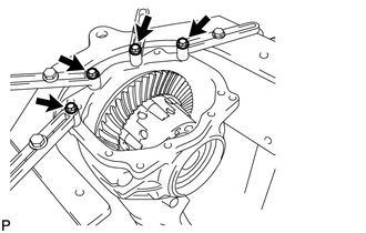
Remove the 4 bolts and rear differential carrier from the overhaul stand.
Note
Clean the contact surface between the rear differential carrier and rear differential carrier cover.
-
-
INSTALL REAR DIFFERENTIAL BREATHER PLUG OIL DEFLECTOR
-
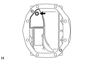
Install the rear differential breather plug oil deflector to the rear differential carrier cover with the bolt.
- Torque:
- 7.0 N*m { 71 kgf*cm, 62 in.*lbf }
-
-
INSTALL REAR DIFFERENTIAL CARRIER STRAIGHT PIN
Tech Tips
It is not necessary to remove a rear differential carrier straight pin unless it is being replaced.
-
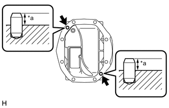
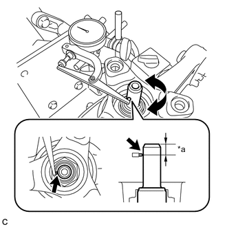
*a Protrusion Using a plastic hammer, install the 2 rear differential carrier straight pins to the rear differential carrier cover.
Protrusion 10 to 12 mm (0.394 to 0.472 in.)
-
-
INSTALL REAR DIFFERENTIAL CARRIER COVER
-
Remove any old seal packing from the rear differential carrier and rear differential carrier cover using a scraper and wire brush. Then remove any oil with non-residue solvent or equivalent.
Note
Do not damage the contact surface.
-
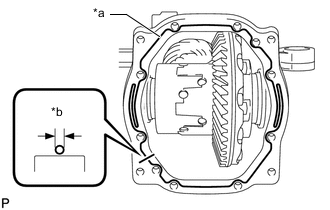
*a Seal Packing *b 2 to 3 mm (0.0787 to 0.118 in.) Apply seal packing to the rear differential carrier as shown in the illustration.
Seal Packing Toyota Genuine Seal Packing 1281, Three bond 1281 or equivalent Tech Tips
-
Apply seal packing in a continuous bead 2 to 3 mm (0.0787 to 0.118 in.) in diameter.
-
Stop applying seal packing after allowing it to overlap with the beginning of the bead by at least 10 mm (0.394 in.).
-
Install the rear differential carrier cover within 3 minutes of applying seal packing. If the rear differential carrier cover is not installed within 3 minutes of applying seal packing, completely remove and then reapply seal packing.
-
After installing the rear differential carrier cover, do not add oil within 1 hour or allow rapid acceleration or deceleration within 12 hours.
-
-
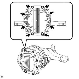
Install the rear differential carrier cover with the 8 bolts.
- Torque:
- 46.6 N*m { 475 kgf*cm, 34 ft.*lbf }
-
-
INSTALL REAR DIFFERENTIAL BREATHER PLUG
-
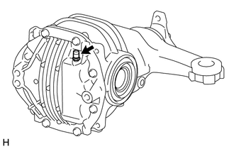
Install the rear differential breather plug to the rear differential carrier cover.
- Torque:
- 20.6 N*m { 210 kgf*cm, 15 ft.*lbf }
-