| DTC Code | DTC Name |
|---|---|
| C2A24 | RH Clutch Torque Map Learning Malfunction |
| C2A25 | LH Clutch Torque Map Learning Malfunction |
DESCRIPTION
The torque vectoring differential ECU assembly has a clutch torque map and periodically performs map learning based on recent driving conditions when the engine switch is turned off.
If an abnormal learning value or an abnormally large difference is detected during map learning, a DTC is stored.
| DTC No. | Detection Item | DTC Detection Condition | Trouble Area | Warning Indicate |
|---|---|---|---|---|
| C2A24 | RH Clutch Torque Map Learning Malfunction | Diagnosis Condition:
Abnormal condition:
Malfunction Time:
Trip logic:
|
|
|
| C2A25 | LH Clutch Torque Map Learning Malfunction | Diagnosis Condition:
Abnormal condition:
Malfunction Time:
Trip logic:
|
|
|
CAUTION / NOTICE / HINT
-
If the torque vectoring differential ECU assembly has been replaced, perform "All Learning".
-
If the torque transfer module motor sub-assembly has been replaced or removed and installed, perform "Motor Exchange Learning".
-
If the torque vectoring differential FDU (Final Drive Unit) has been replaced, perform "ASSY Exchange Learning".
PROCEDURE
- Click here
CHECK DTC OUTPUT (TVD)
-
Connect the GTS to the DLC3.
-
Turn the engine switch on (IG).
-
Enter the following menus: Chassis / TVD / Trouble Codes.
-
Check for DTCs.
- Chassis > TVD > Trouble Codes
-
-
Result Result Proceed to DTC C2A24 is output. A DTC C2A25 is output. B -
Turn the engine switch off.
-
- Click here
READ VALUE USING GTS (RH OIL TEMPERATURE)
-
Disconnect the A torque transfer module motor sub-assembly (RH side) connector.
-
Connect the GTS to the DLC3.
-
Turn the engine switch on (IG).
-
Enter the following menus: Chassis / TVD / Data List / RH Oil Temperature.
- Chassis > TVD > Data List
Tester Display RH Oil Temperature -
-
-
-
- Chassis > TVD > Data List
-

*1 Torque Transfer Module Motor Sub-assembly (RH Side) *a Temperature Sensor (RH Side) Connector Read the Data List when there is an open or short in the temperature sensor (RH side) circuit.
Standard Resistance Tester Display Condition Specified Condition RH Oil Temperature Open between TMPR and TMGR Below -40 °C (-40 °F) Short between TMPR and TMGR 200 °C (392 °F) or higher -
Turn the engine switch off.
-
Reconnect the A torque transfer module motor sub-assembly (RH side) connector.
Result Proceed to OK NG
- OKClick here
- NGClick here
-
- Click here
INSPECT TEMPERATURE SENSOR (RH SIDE)
-
Disconnect the A torque transfer module motor sub-assembly (RH side) connector.
-
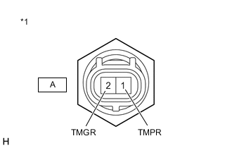
*1 Temperature Sensor (RH Side) Measure the resistance according to the value(s) in the table below.
Standard Resistance Tester Connection Condition Specified Condition A-1 (TMPR) - Body ground Always 10 kΩ or higher A-1 (TMPR) - A-2 (TMGR) 0 °C (32 °F) to 155 °C (311 °F) 0.2 to 30.8 kΩ -
Reconnect the A torque transfer module motor sub-assembly (RH side) connector.
Result Proceed to OK NG
- OK
REPLACE TORQUE VECTORING DIFFERENTIAL FDU (FINAL DRIVE UNIT)Click here
- NG
REPLACE TEMPERATURE SENSOR (RH SIDE)Click here
-
- Click here
CHECK TORQUE TRANSFER MODULE MOTOR SUB-ASSEMBLY (RH SIDE) (HARNESS AND CONNECTOR)
-
Remove the torque vectoring differential FDU (Final Drive Unit).
-
Disconnect the V5 and A torque transfer module motor sub-assembly (RH side) connectors.
-

*1 Torque Transfer Module Motor Sub-assembly (RH Side) *a Temperature Sensor (RH Side) Connector *b TVD Sensor Connector Measure the resistance according to the value(s) in the table below.
Standard Resistance (Check for Open) Tester Connection Condition Specified Condition V5-5 (TMPR) - A-1 (TMPR) Always Below 1 Ω V5-10 (TMGR) - A-2 (TMGR) Always Below 1 Ω Standard Resistance (Check for Short) Tester Connection Condition Specified Condition A-1 (TMPR) - Body ground Always 10 kΩ or higher A-1 (TMPR) - A-2 (TMGR) Always 10 kΩ or higher -
Reconnect the V5 and A torque transfer module motor sub-assembly (RH side) connectors.
-
Install the torque vectoring differential FDU (Final Drive Unit).
Result Proceed to OK NG
- OKClick here
- NG
REPLACE TORQUE TRANSFER MODULE MOTOR SUB-ASSEMBLY (RH SIDE)Click here
-
- Click here
CHECK HARNESS AND CONNECTOR (TORQUE VECTORING DIFFERENTIAL ECU ASSEMBLY - TORQUE TRANSFER MODULE MOTOR SUB-ASSEMBLY (RH SIDE))
-
Disconnect the V3 torque vectoring differential ECU assembly connector.
-
Remove the torque vectoring differential FDU (Final Drive Unit).
-
Disconnect the V5 torque transfer module motor sub-assembly (RH Side) connector.
-
Measure the resistance according to the value(s) in the table below.
Standard Resistance (Check for Open) Tester Connection Condition Specified Condition V3-15 (OTR) - V5-5 (TMPR) Always Below 1 Ω V3-5 (OTRG) - V5-10 (TMGR) Always Below 1 Ω Standard Resistance (Check for Short) Tester Connection Condition Specified Condition V5-5 (TMPR) - Body ground Always 10 kΩ or higher V5-5 (TMPR) - V5-10 (TMGR) Always 10 kΩ or higher -
Reconnect the V5 torque transfer module motor sub-assembly (RH Side) connector.
-
Install the torque vectoring differential FDU (Final Drive Unit).
-
Reconnect the V3 torque vectoring differential ECU assembly connector.
Result Proceed to OK NG
- OK
REPLACE TORQUE VECTORING DIFFERENTIAL ECU ASSEMBLYClick here
- NG
REPAIR OR REPLACE HARNESS OR CONNECTOR
-
- Click here
READ VALUE USING GTS (LH OIL TEMPERATURE)
-
Disconnect the B torque transfer module motor sub-assembly (LH side) connector.
-
Connect the GTS to the DLC3.
-
Turn the engine switch on (IG).
-
Enter the following menus: Chassis / TVD / Data List / LH Oil Temperature.
- Chassis > TVD > Data List
Tester Display LH Oil Temperature -
-
-
-
- Chassis > TVD > Data List
-
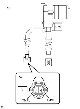
*1 Torque Transfer Module Motor Sub-assembly (LH Side) *a Temperature Sensor (LH Side) Connector Read the Data List when there is an open or short in the temperature sensor (LH side) circuit.
Standard Resistance Tester Display Condition Specified Condition LH Oil Temperature Open between TMPL and TMGL Below -40 °C (-40 °F) Short between TMPL and TMGL 200 °C (392 °F) or higher -
Turn the engine switch off.
-
Reconnect the B torque transfer module motor sub-assembly (LH side) connector.
Result Proceed to OK NG
- OKClick here
- NGClick here
-
- Click here
INSPECT TEMPERATURE SENSOR (LH SIDE)
-
Disconnect the B torque transfer module motor sub-assembly (LH side) connector.
-
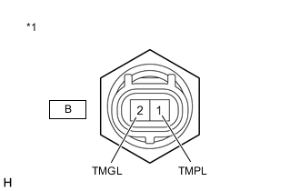
*1 Temperature Sensor (LH Side) Measure the resistance according to the value(s) in the table below.
Standard Resistance Tester Connection Condition Specified Condition B-1 (TMPL) - Body ground Always 10 kΩ or higher B-1 (TMPL) - B-2 (TMGL) 0 °C (32 °F) to 155 °C (311 °F) 0.2 to 30.8 kΩ -
Reconnect the B torque transfer module motor sub-assembly (LH side) connector.
Result Proceed to OK NG
- OK
REPLACE TORQUE VECTORING DIFFERENTIAL FDU (FINAL DRIVE UNIT)Click here
- NG
REPLACE TEMPERATURE SENSOR (LH SIDE)Click here
-
- Click here
CHECK TORQUE TRANSFER MODULE MOTOR SUB-ASSEMBLY (LH SIDE) (HARNESS AND CONNECTOR)
-
Remove the torque vectoring differential FDU (Final Drive Unit).
-
Disconnect the V7 and B torque transfer module motor sub-assembly (LH side) connectors.
-
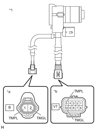
*1 Torque Transfer Module Motor Sub-assembly (LH Side) *a Temperature Sensor (LH Side) Connector *b TVD Sensor Connector Measure the resistance according to the value(s) in the table below.
Standard Resistance (Check for Open) Tester Connection Condition Specified Condition V7-5 (TMPL) - B-1 (TMPL) Always Below 1 Ω V7-10 (TMGL) - B-2 (TMGL) Always Below 1 Ω Standard Resistance (Check for Short) Tester Connection Condition Specified Condition B-1 (TMPL) - Body ground Always 10 kΩ or higher B-1 (TMPL) - B-2 (TMGL) Always 10 kΩ or higher -
Reconnect the V7 and B torque transfer module motor sub-assembly (LH side) connectors.
-
Install the torque vectoring differential FDU (Final Drive Unit).
Result Proceed to OK NG
- OKClick here
- NG
REPLACE TORQUE TRANSFER MODULE MOTOR SUB-ASSEMBLY (LH SIDE)Click here
-
- Click here
CHECK HARNESS AND CONNECTOR (TORQUE VECTORING DIFFERENTIAL ECU ASSEMBLY - TORQUE TRANSFER MODULE MOTOR SUB-ASSEMBLY (LH SIDE))
-
Disconnect the V3 torque vectoring differential ECU assembly connector.
-
Remove the torque vectoring differential FDU (Final Drive Unit).
-
Disconnect the V7 torque transfer module motor sub-assembly (LH side) connector.
-
Measure the resistance according to the value(s) in the table below.
Standard Resistance (Check for Open) Tester Connection Condition Specified Condition V3-6 (OTL) - V7-5 (TMPL) Always Below 1 Ω V3-16 (OTLG) - V7-10 (TMGL) Always Below 1 Ω Standard Resistance (Check for Short) Tester Connection Condition Specified Condition V7-5(TMPL) - Body ground Always 10 kΩ or higher V7-5 (TMPL) - V7-10 (TMGL) Always 10 kΩ or higher -
Reconnect the V7 torque transfer module motor sub-assembly (LH side) connector.
-
Install the torque vectoring differential FDU (Final Drive Unit).
-
Reconnect the V3 torque vectoring differential ECU assembly connector.
Result Proceed to OK NG
- OK
REPLACE TORQUE VECTORING DIFFERENTIAL ECU ASSEMBLYClick here
- NG
REPAIR OR REPLACE HARNESS OR CONNECTOR
-