CAUTION / NOTICE / HINT
-
Use the same procedure for the RH side and LH side.
-
The following procedure is for the LH side.
PROCEDURE
- Click here
INSTALL REAR AXLE HUB AND BEARING ASSEMBLY
-
Hold the rear axle carrier sub-assembly between aluminum plates in a vise.
Note:Do not overtighten the vise.
-
Install the rear axle hub and bearing assembly and parking brake plate sub-assembly to the rear axle carrier sub-assembly with the 4 bolts.
75 N*m 765 kgf*cm 55 ft.*lbf
-
- Click here
INSTALL REAR NO. 1 WHEEL BEARING DUST DEFLECTOR
-
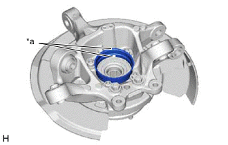
*a Hole Set a new rear No. 1 wheel bearing dust deflector to the rear axle carrier sub-assembly while aligning the hole for the rear speed sensor in the rear No. 1 wheel bearing dust deflector with the hole of the rear axle carrier sub-assembly.
-
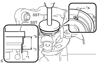
*1 Rear No. 1 Wheel Bearing Dust Deflector *a Hole *b Edge of Rear No. 1 Wheel Bearing Dust Deflector *c Edge of Rear Axle Hub Bearing Outer Race Using SST and a press, install the rear No. 1 wheel bearing dust deflector to the rear axle carrier sub-assembly as specified.
09950-70010 09951-07150 09951-01000 Standard Length 23.3 to 23.9 mm (0.918 to 0.940 in.)
-
- Click here
INSTALL REAR AXLE ASSEMBLY
-
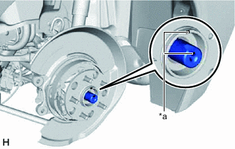
*a Matchmark Install the rear axle assembly to the rear drive shaft assembly.
Note:Align the matchmarks on the rear drive shaft assembly and rear axle hub and bearing assembly.
-
- Click here
TEMPORARILY INSTALL REAR NO. 2 UPPER CONTROL ARM ASSEMBLY
- Click here
TEMPORARILY INSTALL REAR NO. 1 UPPER CONTROL ARM ASSEMBLY
- Click here
INSTALL REAR LOWER COIL SPRING INSULATOR
- Click here
INSTALL REAR UPPER COIL SPRING INSULATOR
- Click here
INSTALL REAR COIL SPRING
- Click here
TEMPORARILY INSTALL REAR SHOCK ABSORBER ASSEMBLY
- Click here
INSTALL REAR STABILIZER LINK ASSEMBLY
- Click here
TEMPORARILY INSTALL REAR NO. 1 SUSPENSION ARM ASSEMBLY
-
Temporarily install the rear No. 1 suspension arm assembly to the rear axle carrier sub-assembly with the bolt and nut.
Note:Because the nut has its own stopper, do not turn the nut. Tighten the bolt with the nut secured.
Tip:Insert the bolt with the threaded end facing the front of the vehicle.
-
- Click here
CONNECT REAR STEERING TIE ROD ASSEMBLY
- Click here
INSTALL PARKING BRAKE ASSEMBLY
- Click here
INSTALL REAR DISC
- Click here
INSTALL REAR DISC BRAKE CALIPER ASSEMBLY
-
Install the rear disc brake caliper assembly with the pad wear indicator wire assembly to the rear axle carrier sub-assembly with the 2 bolts.
125 N*m 1275 kgf*cm 92 ft.*lbf
-
- Click here
TEMPORARILY INSTALL REAR AXLE SHAFT NUT
-
Clean the threaded parts on the rear drive shaft assembly and a new rear axle shaft nut using non-residue solvent.
Note:
-
Be sure to perform this work even when using a new rear drive shaft assembly.
-
Keep the threaded parts free of oil and foreign matter.
-
-
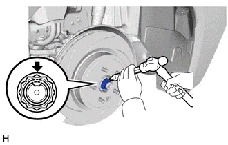
Using a 32 mm socket wrench, while applying the brakes, temporarily install the rear axle shaft nut.
290 N*m 2957 kgf*cm 214 ft.*lbf Note:Stake the rear axle shaft nut after inspecting for looseness and runout in the following steps.
Tip:Keep depressing the brake pedal to prevent the rear drive shaft assembly from rotating.
-
- Click here
SEPARATE REAR DISC BRAKE CALIPER ASSEMBLY
-
Remove the 2 bolts and separate the rear disc brake caliper assembly with the pad wear indicator wire assembly from the rear axle carrier sub-assembly.
Note:Use wire or an equivalent tool to keep the rear disc brake caliper assembly from hanging by the rear flexible hose.
-
- Click here
REMOVE REAR DISC
- Click here
INSPECT REAR AXLE HUB BEARING LOOSENESS
- Click here
INSPECT REAR AXLE HUB RUNOUT
- Click here
INSTALL REAR DISC
- Click here
INSTALL PARKING BRAKE SHOE ADJUSTING HOLE PLUG
- Click here
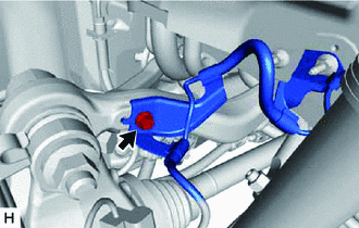
INSTALL REAR SPEED SENSOR
-
Install the rear speed sensor to the rear axle carrier sub-assembly with the 2 bolts.
8.5 N*m 87 kgf*cm 75 in.*lbf
-
- Click here
INSTALL REAR DISC BRAKE CALIPER ASSEMBLY
- Click here
INSTALL REAR AXLE SHAFT NUT
-
Using a chisel and hammer, stake the rear axle shaft nut.
-
- Click here
STABILIZE SUSPENSION
- Click here
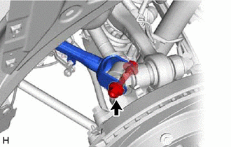
INSTALL REAR NO. 2 UPPER CONTROL ARM ASSEMBLY
-

Install the rear No. 2 upper control arm assembly (rear axle assembly side) with the nut.
190 N*m 1937 kgf*cm 140 ft.*lbf Note:Because the bolt has its own stopper, do not turn the bolt. Tighten the nut with the bolt secured.
-
Install the rear speed sensor to the rear No. 2 upper control arm assembly with the bolt.
8.5 N*m 87 kgf*cm 75 in.*lbf
-
- Click here
INSTALL REAR NO. 1 UPPER CONTROL ARM ASSEMBLY
-
Install the rear No. 1 upper control arm assembly (rear axle assembly side) with the nut.
150 N*m 1530 kgf*cm 111 ft.*lbf Note:Because the bolt has its own stopper, do not turn the bolt. Tighten the nut with the bolt secured.
-
- Click here
INSTALL REAR NO. 2 SUSPENSION ARM ASSEMBLY
- Click here
INSTALL REAR SHOCK ABSORBER ASSEMBLY
- Click here
INSTALL REAR NO. 1 SUSPENSION ARM ASSEMBLY
- Click here
INSTALL REAR SUSPENSION ARM COVER
- Click here
INSTALL REAR HEIGHT CONTROL SENSOR SUB-ASSEMBLY
- Click here
ADJUST PARKING BRAKE
- Click here
INSTALL REAR WHEEL
- Click here
INSPECT AND ADJUST REAR WHEEL ALIGNMENT
- Click here
CHECK FOR SPEED SENSOR SIGNAL
- Click here
INITIALIZE HEIGHT CONTROL SENSOR SIGNAL
- Click here
ADJUST HEADLIGHT AIMING