REAR DRIVE SHAFT ASSEMBLY INSTALLATION

PROCEDURE
-
INSTALL REAR DRIVE SHAFT ASSEMBLY LH
-
Install a new shaft snap ring.
Note
Face the end gap of the shaft snap ring downward.
-
for LSD:
-
Coat the splines of the rear drive inboard joint assembly with differential gear oil LX.
-
-
for Torque Vectoring Differential:
-
Coat the splines of the rear drive inboard joint assembly with ATF WS.
-
-
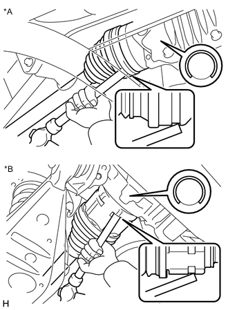
*A for LSD *B for Torque Vectoring Differential Align the inboard joint splines, and using a brass bar and a hammer, install the rear drive shaft assembly LH.
Note
-
Face the end gap of the shaft snap ring downward.
-
Do not damage the rear drive shaft oil seal.
-
Do not damage the inboard joint boot.
-
Install the rear drive shaft assembly LH while keeping it level.
Tech Tips
Confirm whether the drive shaft is securely driven in by checking the reaction force and sound.
-
-
-
INSTALL REAR DRIVE SHAFT ASSEMBLY RH
Tech Tips
Use the same procedure as for the LH side.
-
ADD TORQUE TRANSFER MODULE FLUID (for Torque Vectoring Differential)
-
INSPECT FOR TORQUE TRANSFER MODULE FLUID AND DIFFERENTIAL OIL LEAK (for Torque Vectoring Differential)
-
INSTALL NO. 3 PARKING BRAKE CABLE ASSEMBLY (for Torque Vectoring Differential)
for LH Side:
-
INSTALL REAR AXLE ASSEMBLY LH
-
INSTALL REAR AXLE ASSEMBLY RH
Tech Tips
Use the same procedure as for the LH side.
-
INSTALL REAR SUSPENSION MEMBER BRACE LH
-
Install the rear suspension member brace LH with the 2 new bolts.
- Torque:
- 56 N*m { 571 kgf*cm, 41 ft.*lbf }
-
-
INSTALL REAR SUSPENSION MEMBER BRACE RH
Tech Tips
Use the same procedure as for the LH side.