AUTOMATIC TRANSMISSION UNIT REASSEMBLY

PROCEDURE
-
BEARING POSITION
-
Check each bearing position and installation direction.
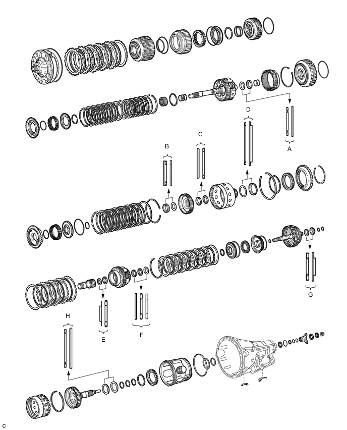
Bearing Position Position Front Race Diameter
Inside/Outside
Thrust Bearing Diameter
Inside/Outside
Rear Race Diameter
Inside/Outside
(A) - 36.2 mm (1.43 in.) / 58.2 mm (2.29 in.) 44.0 mm (1.73 in.) / 62.0 mm (2.44 in.) (B) - 34.5 mm (1.36 in.) / 49.4 mm (1.94 in.) 36.6 mm (1.44 in.) / 51.9 mm (2.04 in.) (C) 46.5 mm (1.83 in.) / 60.1 mm (2.37 in.) 47.0 mm (1.85 in.) / 61.9 mm (2.44 in.) - (D) - 71.9 mm (2.83 in.) / 85.6 mm (3.37 in.) 72.7 mm (2.86 in.) / 89.2 mm (3.51 in.) (E) 30.0 mm (1.18 in.) / 49.9 mm (1.96 in.) 31.0 mm (1.22 in.) / 53.1 mm (2.09 in.) - (F) 31.5 mm (1.24 in.) / 54.3 mm (2.14 in.) 28.7 mm (1.13 in.) / 52.3 mm (2.06 in.) 28.7 mm (1.13 in.) / 50.4 mm (1.98 in.) (G) - 30.5 mm (1.20 in.) / 55.7 mm (2.19 in.) 33.5 mm (1.32 in.) / 59.0 mm (2.32 in.) (H) - 58.9 mm (2.32 in.) / 76.7 mm (3.02 in.) 62.0 mm (2.44 in.) / 82.5 mm (3.25 in.)
-
-
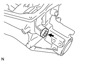
INSTALL OUTPUT SHAFT REAR RADIAL BALL BEARING
-
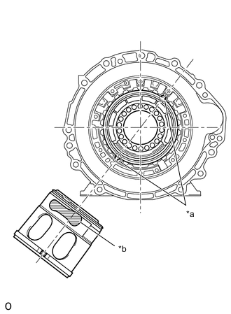
Using SST, install a new output shaft rear radial ball bearing to the automatic transmission case sub-assembly.
- SST
- 09316-60011 ( 09316-00011, 09316-00021 )
-
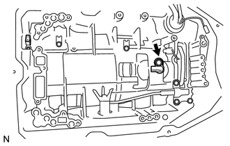
Using snap ring pliers, install the snap ring to the automatic transmission case sub-assembly.
-
-
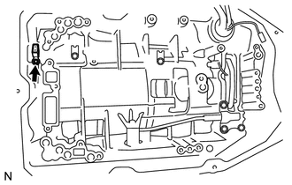
INSTALL BRAKE PLATE STOPPER SPRING
-
Install the 2 brake plate stopper springs to the automatic transmission case sub-assembly.
-
-
INSTALL NO. 2 BRAKE PISTON
-
Coat 3 new O-rings with ATF, and install them to the No. 2 brake piston.
-
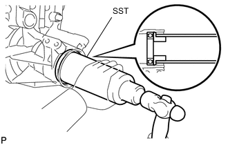
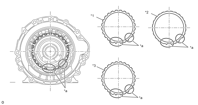
*a Cutout *b Parking Hole Install the No. 2 brake piston to the automatic transmission case sub-assembly.
Tech Tips
Ensure that the parking hole of the No. 2 brake piston is positioned correctly by aligning the protrusions of the No. 2 brake piston with the cutouts of the automatic transmission case sub-assembly as shown in the illustration
-
Install the 2nd brake piston return spring sub-assembly to the automatic transmission case sub-assembly.
-
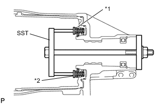
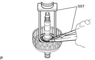
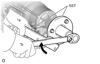
*1 2nd Brake Piston Return Spring Sub-assembly *2 Snap Ring Set SST on the 2nd brake piston return spring sub-assembly and tighten SST to compress the 2nd brake piston return spring sub-assembly.
- SST
- 09380-50010 ( 09381-05010, 09381-05020 )
-
Using SST, install the snap ring to the automatic transmission case sub-assembly.
- SST
- 09350-30020 ( 09350-07070 )
-
-
INSPECT PACK CLEARANCE OF NO. 2 BRAKE
-
INSTALL DIRECT CLUTCH PISTON
-
Coat a new O-ring with ATF and install it to the direct clutch drum sub-assembly.
-
Coat a new O-ring with ATF and install it to the direct clutch piston.
-
*1 Direct Clutch Piston Install the direct clutch piston to the direct clutch drum sub-assembly.
-
Coat a new O-ring with ATF and install it to the No. 2 clutch balancer.
-
*1 No. 2 Clutch Balancer *2 Direct Clutch Return Spring Sub-assembly Install the direct clutch return spring sub-assembly and No. 2 clutch balancer to the direct clutch drum sub-assembly.
-
Set SST on the No. 2 clutch balancer and compress the direct clutch return spring sub-assembly with a press.
- SST
- 09387-00020
-
Using SST, install the snap ring to the direct clutch drum sub-assembly.
- SST
- 09350-30020 ( 09350-07070 )
-
-
INSTALL NO. 2 CLUTCH DISC
-
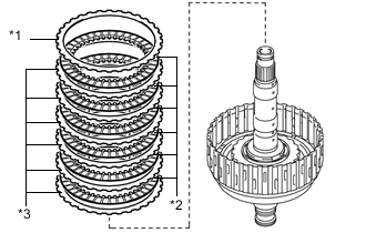
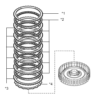
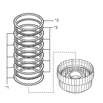
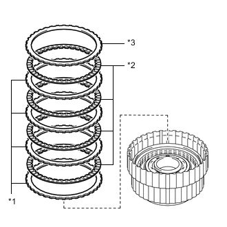
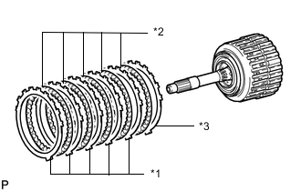
*1 No. 2 Clutch Flange *2 No. 2 Clutch Disc *3 No. 2 Clutch Plate Install the 6 No. 2 clutch plates, 6 No. 2 clutch discs and No. 2 clutch flange to the direct clutch drum sub-assembly.
Note
Make sure that the No. 2 clutch discs, No. 2 clutch plates and No. 2 clutch flange are installed in the correct order.
-
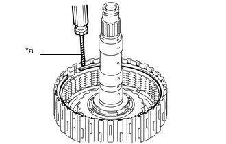
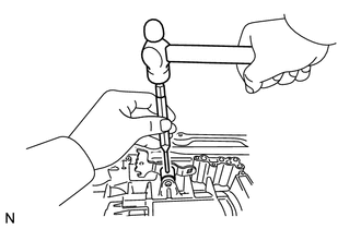
*a Protective Tape Using a screwdriver, install the snap ring to the direct clutch drum sub-assembly.
Note
Be careful not to damage the direct clutch drum sub-assembly.
Tech Tips
Tape the screwdriver tip before use.
-
-
INSPECT PACK CLEARANCE OF NO. 2 CLUTCH
-
INSTALL MULTIPLE DISC CLUTCH ASSEMBLY
-
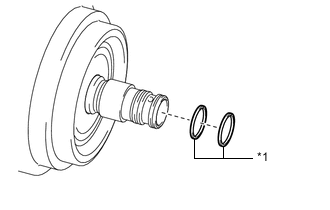
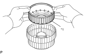
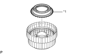
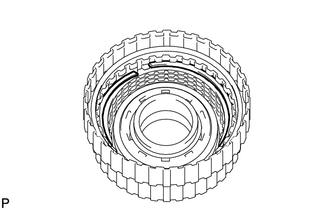
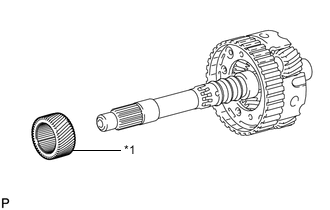
*1 Oil Seal Ring Coat 2 new oil seal rings with ATF and install them to the multiple disc clutch assembly.
Note
Do not expand the gap of the oil seal rings excessively.
-
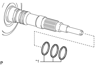
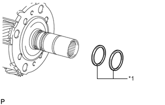
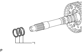
*1 Oil Seal Ring Coat 3 new oil seal rings with ATF and install them to the output shaft sub-assembly.
Note
Do not expand the gap of the oil seal rings excessively.
-
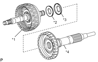
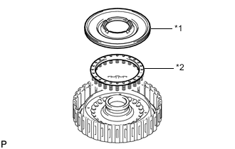
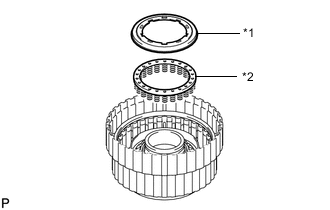
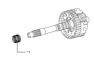
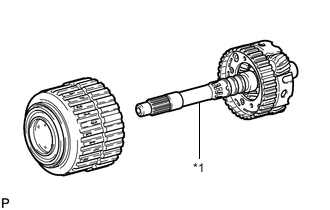
*1 Multiple Disc Clutch Assembly *2 Thrust Needle Roller Bearing *3 Thrust Bearing Race *4 Output Shaft Sub-assembly Install the thrust needle roller bearing and thrust bearing race to the multiple disc clutch assembly.
Thrust Needle Roller Bearing and Thrust Bearing Race Diameter Item Inside Outside Thrust needle roller bearing 30.5 mm (1.20 in.) 55.7 mm (2.19 in.) Thrust bearing race 33.5 mm (1.32 in.) 59.0 mm (2.32 in.) -
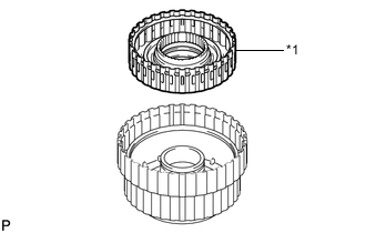
Install the multiple disc clutch assembly to the output shaft sub-assembly.
-
-
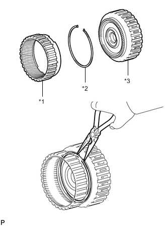
INSTALL REAR PLANETARY RING GEAR
-
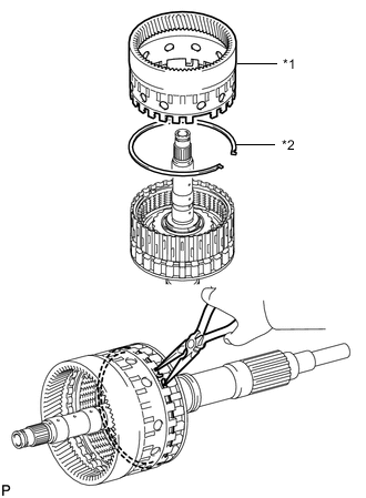
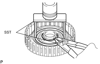
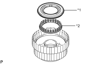
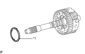
*1 Rear Planetary Ring Gear *2 Snap Ring Install the snap ring to the groove of the output shaft sub-assembly.
-
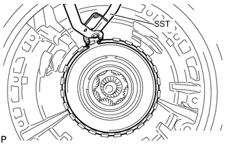
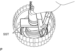
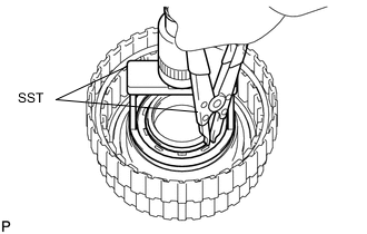
Using needle-nose pliers, contract the snap ring and install the rear planetary ring gear to the output shaft sub-assembly.
-
-
INSTALL MULTIPLE DISC CLUTCH ASSEMBLY WITH REAR PLANETARY RING GEAR AND OUTPUT SHAFT SUB-ASSEMBLY
-
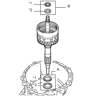
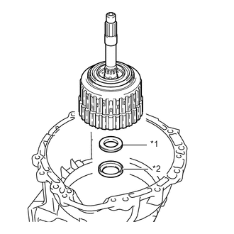
*1 Thrust Needle Roller Bearing *2 Thrust Bearing Race Install the 2 thrust needle roller bearings, 2 thrust bearing races and multiple disc clutch assembly with rear planetary ring gear and output shaft sub-assembly to the automatic transmission case sub-assembly.
Thrust Needle Roller Bearing and Thrust Bearing Race Diameter Item Inside Outside Thrust bearing race (A) 62.0 mm (2.44 in.) 82.5 mm (3.25 in.) Thrust needle roller bearing (A) 58.9 mm (2.32 in.) 76.7 mm (3.02 in.) Thrust bearing race (B) 28.7 mm (1.13 in.) 50.4 mm (1.98 in.) Thrust needle roller bearing (B) 28.7 mm (1.13 in.) 52.3 mm (2.06 in.)
-
-
INSTALL AUTOMATIC TRANSMISSION REAR OIL SEAL
-
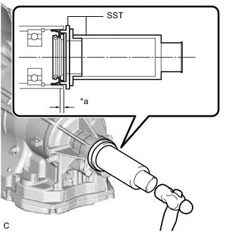
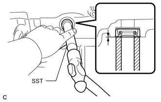
*a Depth Using SST and a hammer, install a new automatic transmission rear oil seal to the automatic transmission case sub-assembly.
- SST
- 09316-60011 ( 09316-00011, 09316-00041 )
- 09316-12010
Standard Depth 3.3 to 3.7 mm (0.130 to 0.146 in.) -
Coat the lip of the automatic transmission rear oil seal with MP grease.
-
-
INSTALL AUTOMATIC TRANSMISSION FLANGE YOKE ASSEMBLY
-
Using SST and a hammer, install a new oil seal.
- SST
- 09517-36010
Standard Depth 0 to 0.3 mm (0 to 0.0118 in.) -
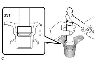
*a Depth Coat the lip of the oil seal with MP grease.
-
Install the rear cover sleeve and 2 rear No. 1 output shaft bearing spacers to the automatic transmission flange yoke assembly.
-
Install the automatic transmission flange yoke assembly to the automatic transmission case sub-assembly.
-
*a Hold *b Turn Using SST and a 30 mm deep socket wrench, install a new lock nut.
- SST
- 09330-00021
- 09950-30012 ( 09955-03040 )
- Torque:
- 135 N*m { 1377 kgf*cm, 100 ft.*lbf }
-
-
SELECT REAR COVER SLEEVE
-
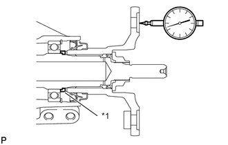
*1 Rear Cover Sleeve Using a dial indicator, measure the output shaft end play.
Standard End Play 0.21 to 0.36 mm (0.00827 to 0.0142 in.) If the end play is not as specified, select and install an appropriate rear cover sleeve that will bring the end play within the specified range.
Tech Tips
There are 15 rear cover sleeves of different thicknesses.
Rear Cover Sleeve Thickness Part No. Mark Thickness 35155-50230 00 1.675 to 1.725 mm (0.0659 to 0.0679 in.) 35155-50080 02 1.725 to 1.775 mm (0.0679 to 0.0699 in.) 35155-50090 03 1.775 to 1.825 mm (0.0699 to 0.0719 in.) 35155-50100 04 1.825 to 1.875 mm (0.0719 to 0.0738 in.) 35155-50110 05 1.875 to 1.925 mm (0.0738 to 0.0758 in.) 35155-50120 06 1.925 to 1.975 mm (0.0758 to 0.0778 in.) 35155-50130 07 1.975 to 2.025 mm (0.0778 to 0.0797 in.) 35155-50140 08 2.025 to 2.075 mm (0.0797 to 0.0817 in.) 35155-50150 09 2.075 to 2.125 mm (0.0817 to 0.0837 in.) 35155-50160 10 2.125 to 2.175 mm (0.0837 to 0.0856 in.) 35155-50170 11 2.175 to 2.225 mm (0.0856 to 0.0876 in.) 35155-50180 12 2.225 to 2.275 mm (0.0876 to 0.0896 in.) 35155-50190 13 2.275 to 2.325 mm (0.0896 to 0.0915 in.) 35155-50200 14 2.325 to 2.375 mm (0.0915 to 0.0935 in.) 35155-50210 15 2.375 to 2.425 mm (0.0935 to 0.0955 in.) -
Using a chisel and hammer, securely stake the lock nut.
-
-
INSTALL REAR PLANETARY GEAR ASSEMBLY
-
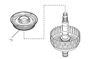
*1 Thrust Needle Roller Bearing *2 Rear Planetary Gear Assembly *3 Thrust Bearing Race Install the thrust bearing race, rear planetary gear assembly and thrust needle roller bearing to the automatic transmission case sub-assembly.
Thrust Needle Roller Bearing and Thrust Bearing Diameter Item Inside Outside Thrust bearing race 31.5 mm (1.24 in.) 54.3 mm (2.14 in.) Thrust needle roller bearing 31.0 mm (1.22 in.) 53.1 mm (2.09 in.) Note
Before installing the rear planetary gear assembly, apply ATF to the contact surfaces of the rear planetary gear assembly bushing. After installation, check that the rear planetary gear assembly rotates smoothly.
-
-
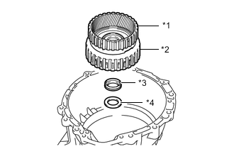
INSTALL REAR PLANETARY SUN GEAR SUB-ASSEMBLY
-
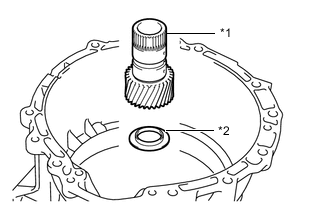
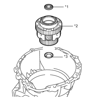
*1 Rear Planetary Sun Gear Assembly *2 Thrust Bearing Race Install the thrust bearing race and rear planetary sun gear assembly to the automatic transmission case sub-assembly.
Thrust Bearing Race Diameter Item Inside Outside Thrust bearing race 30.0 mm (1.18 in.) 49.9 mm (1.96 in.) Note
Before installing the rear planetary sun gear assembly, apply ATF to the contact surfaces of the rear planetary sun gear assembly bushing. After installation, check that the rear planetary sun gear assembly rotates smoothly.
-
-
INSTALL NO. 2 BRAKE DISC
-
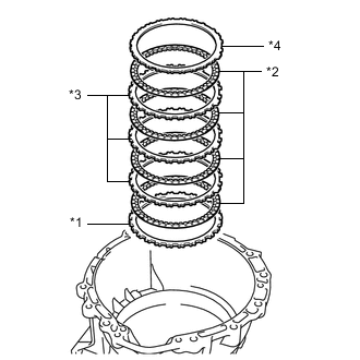
*1 No. 2 Brake Flange *2 No. 2 Brake Disc *3 No. 2 Brake Plate *4 Brake Plate Install the No. 2 brake flange, 4 No. 2 brake discs, 3 No. 2 brake plates and brake plate to the automatic transmission case sub-assembly.
Note
Make sure that the No. 2 brake discs, No. 2 brake plates, brake plate and No. 2 brake flange are installed in the correct order.
Tech Tips
Align the protrusions of the No. 2 brake flange, No. 2 brake plates and brake plate with the cutouts of the automatic transmission case sub-assembly.
*1 No. 2 Brake Flange *2 Brake Plate *3 No. 2 Brake Plate - - *a Protrusion - -
-
-
INSTALL NO. 1 ONE-WAY CLUTCH
-
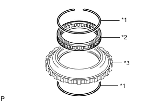
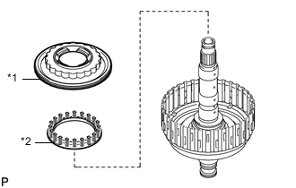
*1 Snap Ring *2 No. 1 One-way Clutch *3 One-way Clutch Outer Race Using a screwdriver, install the No. 1 one-way clutch and 2 snap rings to the one-way clutch outer race.
Note
Make sure that the No. 1 one-way clutch is installed in the correct direction.
-
-
INSPECT NO. 1 ONE-WAY CLUTCH
-
INSTALL ONE-WAY CLUTCH OUTER RACE WITH NO. 1 ONE-WAY CLUTCH
-
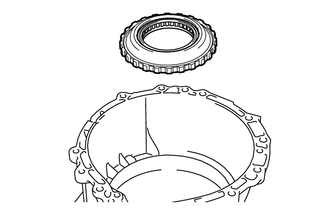
Install the one-way clutch outer race with No. 1 one-way clutch to the automatic transmission case sub-assembly.
-
Using SST, install the snap ring to the automatic transmission case sub-assembly.
- SST
- 09350-30020 ( 09350-07060 )
Note
-
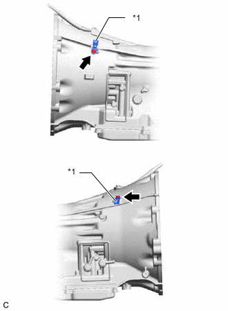
Install the snap ring so that the tapered side is facing out.
-
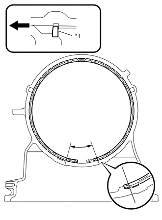
*1 Snap Ring 
Front Side Be sure to orient the snap ring so that the edges do not protrude into one of the cutouts of the automatic transmission case sub-assembly as shown in the illustration.
-
-
INSTALL SUN GEAR INPUT DRUM SUB-ASSEMBLY
-
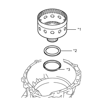
*1 Sun Gear Input Drum Sub-assembly *2 Thrust Needle Roller Bearing *3 Thrust Bearing Race Install the thrust bearing race, thrust needle roller bearing and sun gear input drum sub-assembly to the automatic transmission case sub-assembly.
Thrust Needle Roller Bearing and Thrust Bearing Race Diameter Item Inside Outside Thrust bearing race 72.7 mm (2.86 in.) 89.2 mm (3.51 in.) Thrust needle roller bearing 71.9 mm (2.83 in.) 85.6 mm (3.37 in.) Note
Before installing the sun gear input drum sub-assembly, apply ATF to contact surfaces of the sun gear input drum sub-assembly bushing. After installation, check that the sun gear input drum sub-assembly rotates smoothly.
-
-
INSTALL FORWARD CLUTCH PISTON
-
Coat 2 new O-rings with ATF and install them to the forward clutch piston.
-
*1 Forward Clutch Piston Install the forward clutch piston to the forward clutch drum sub-assembly.
-
Coat a new O-ring with ATF and install it to the No. 1 clutch balancer.
-
*1 No. 1 Clutch Balancer *2 Forward Clutch Return Spring Sub-assembly Install the forward clutch return spring sub-assembly and No. 1 clutch balancer to the forward clutch drum sub-assembly.
-
Set SST on the No. 1 clutch balancer, and compress the forward clutch return spring sub-assembly using a press.
- SST
- 09380-50010 ( 09381-05020 )
Note
Stop the press when the No. 1 clutch balancer is lowered to a place 1 to 2 mm (0.0394 to 0.0787 in.) below the snap ring groove to prevent the forward clutch return spring sub-assembly from being deformed.
-
Using SST, install the snap ring to the forward clutch drum sub-assembly.
- SST
- 09350-30020 ( 09350-07070 )
Note
-
Make sure that the end gap of the snap ring is not aligned with a spring retainer claw.
-
Do not expand the snap ring excessively.
-
-
INSTALL FORWARD MULTIPLE CLUTCH DISC
-
*1 Forward Clutch Flange *2 Forward Multiple Clutch Disc *3 Forward Multiple Clutch Plate *4 Clutch Cushion Plate Install the clutch cushion plate, 6 forward multiple clutch plates, 6 forward multiple clutch discs and forward clutch flange to the forward clutch drum sub-assembly.
Note
-
Install the clutch cushion plate with its marked side facing the forward multiple clutch plates.
-
Make sure that the clutch cushion plate, forward multiple clutch plates, forward multiple clutch discs and forward clutch flange are installed in the correct order.
-
-
Install the snap ring to the forward clutch drum sub-assembly.
-
-
INSPECT PACK CLEARANCE OF FORWARD MULTIPLE CLUTCH
-
INSTALL FRONT PLANETARY RING GEAR
-
*1 Front Planetary Ring Gear *2 Snap Ring *3 Forward Multiple Disc Clutch Assembly Using needle-nose pliers, install the snap ring to the groove of forward multiple disc clutch assembly.
-
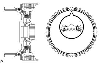
Using needle-nose pliers, contract the snap ring and install the front planetary ring gear to the forward multiple disc clutch assembly.
Note
Confirm that the snap ring is correctly located in the groove of the forward multiple disc clutch assembly as shown in the illustration.
-
-
INSTALL MULTIPLE DISC CLUTCH HUB
-
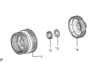
*1 Forward Multiple Disc Clutch Assembly with Front Planetary Ring Gear *2 Thrust Needle Roller Bearing *3 Thrust Bearing Race *4 Multiple Disc Clutch Hub Install the thrust needle roller bearing, thrust bearing race and forward multiple disc clutch assembly with front planetary ring gear to the multiple disc clutch hub.
Thrust Needle Roller Bearing and Thrust Bearing Race Diameter Item Inside Outside Thrust needle roller bearing 34.5 mm (1.36 in.) 49.4 mm (1.94 in.) Thrust bearing race 36.6 mm (1.44 in.) 51.9 mm (2.04 in.)
-
-
INSTALL FORWARD MULTIPLE DISC CLUTCH ASSEMBLY WITH FRONT PLANETARY RING GEAR AND MULTIPLE DISC CLUTCH HUB
-
*1 Front Planetary Ring Gear *2 Forward Multiple Disc Clutch Assembly *3 Thrust Needle Roller Bearing *4 Thrust Bearing Race Install the thrust bearing race, thrust needle roller bearing and forward multiple disc clutch assembly with front planetary ring gear and multiple disc clutch hub to the automatic transmission case sub-assembly.
Thrust Needle Roller Bearing and Thrust Bearing Race Diameter Item Inside Outside Thrust needle roller bearing 47.0 mm (1.85 in.) 61.9 mm (2.44 in.) Thrust bearing race 46.5 mm (1.83 in.) 60.1 mm (2.37 in.) Note
Before installing the forward multiple disc clutch assembly, apply ATF to the contact surfaces of the forward multiple disc clutch assembly bushing. After installation, check that the forward multiple disc clutch assembly rotates smoothly.
-
-
INSTALL OVERDRIVE DIRECT CLUTCH PISTON SUB-ASSEMBLY
-
Coat a new O-ring with ATF and install it to the overdrive direct clutch drum sub-assembly.
-
Coat a new O-ring with ATF and install it to the overdrive direct clutch piston sub-assembly.
-
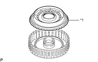
*1 Overdrive Direct Clutch Piston Sub-assembly Install the overdrive direct clutch piston sub-assembly to the overdrive direct clutch drum sub-assembly.
-
Coat a new O-ring with ATF and install it to the No. 3 clutch balancer.
-
*1 No. 3 Clutch Balancer *2 Overdrive Clutch Return Spring Sub-assembly Install the overdrive clutch return spring sub-assembly and No. 3 clutch balancer to the overdrive direct clutch drum sub-assembly.
-
Set SST on the No. 3 clutch balancer, and compress the overdrive clutch return spring sub-assembly using a press.
- SST
- 09380-50010 ( 09381-05020 )
Note
Stop the press when the No. 3 clutch balancer is lowered to a place 1 to 2 mm (0.0394 to 0.0787 in.) below the snap ring groove to prevent the overdrive clutch return spring sub-assembly from being deformed.
-
Using SST, install the snap ring to the overdrive direct clutch drum sub-assembly.
- SST
- 09350-30020 ( 09350-07070 )
Note
-
Make sure that the end gap of the snap ring is not aligned with a spring retainer claw.
-
Do not expand the snap ring excessively.
-
-
INSTALL REVERSE CLUTCH DRUM SUB-ASSEMBLY
-
*1 Reverse Clutch Drum Sub-assembly Coat 3 new O-rings with ATF and install them to the reverse clutch drum sub-assembly.
-
Install the reverse clutch drum sub-assembly to the overdrive direct clutch drum sub-assembly.
-
-
INSTALL REVERSE CLUTCH PISTON
-
*1 Reverse Clutch Piston Coat a new O-ring with ATF and install it to the reverse clutch piston.
-
Install the reverse clutch piston to the overdrive direct clutch drum sub-assembly.
-
*1 Reverse Clutch Balancer *2 Reverse Clutch Return Spring Sub-assembly Install the reverse clutch return spring sub-assembly and reverse clutch balancer to the overdrive direct clutch drum sub-assembly.
-
Set SST on the reverse clutch balancer, and compress the reverse clutch return spring sub-assembly using a press.
- SST
- 09380-50010 ( 09381-05020 )
Note
Stop the press when the reverse clutch balancer is lowered to a place 1 to 2 mm (0.0394 to 0.0787 in.) below the snap ring groove to prevent the reverse clutch return spring sub-assembly from being deformed.
-
Using SST, install the snap ring to the overdrive direct clutch drum sub-assembly.
- SST
- 09350-30020 ( 09350-07070 )
Note
-
Make sure that the end gap of the snap ring is not aligned with a spring retainer claw.
-
Do not expand the snap ring excessively.
-
-
INSTALL REVERSE CLUTCH DISC
-
*1 Reverse Clutch Flange *2 Reverse Clutch Disc *3 Reverse Clutch Plate Install the 5 reverse clutch plates, 5 reverse clutch discs and reverse clutch flange to the reverse clutch drum sub-assembly.
Note
Make sure that the reverse clutch discs, reverse clutch plates and reverse clutch flange are installed in the correct order.
-
Install the snap ring to the reverse clutch drum sub-assembly.
-
-
INSPECT PACK CLEARANCE OF REVERSE CLUTCH
-
INSTALL NO. 3 CLUTCH DISC
-
*1 No. 3 Clutch Plate *2 No. 3 Clutch Disc *3 No. 3 Clutch Flange Install the 4 No. 3 clutch plates, 4 No. 3 clutch discs and No. 3 clutch flange to the overdrive direct clutch drum sub-assembly.
Note
Make sure that the No. 3 clutch discs, No. 3 clutch plates and No. 3 clutch flange are installed in the correct order.
-
Install the snap ring to the overdrive direct clutch drum sub-assembly.
-
-
INSPECT PACK CLEARANCE OF NO. 3 CLUTCH
-
INSTALL FRONT PLANETARY GEAR ASSEMBLY
-
*1 Front Planetary Gear Shaft Snap Ring Coat 2 new front planetary gear shaft snap rings with ATF and install them to the front planetary gear assembly.
Note
Do not expand the gap of the front planetary gear shaft snap rings excessively.
-
*1 Front Planetary Gear Thrust Needle Roller Bearing Install the front planetary gear thrust needle roller bearing to the front planetary gear assembly.
-
*1 Front Planetary Gear Shaft Snap Ring Coat 3 new front planetary gear shaft snap rings with ATF and install them to the front planetary gear assembly.
Note
Do not expand the gap of the front planetary gear shaft snap rings excessively.
-
*1 Planetary Carrier Thrust Washer Install the planetary carrier thrust washer to the front planetary gear assembly.
-
*1 Planetary Sun Gear Install the planetary sun gear to the front planetary gear assembly.
-
*1 Front Planetary Gear Assembly Install the front planetary gear assembly with the front planetary sun gear to the overdrive and reverse multiple disc clutch assembly.
-
-
INSPECT PACK CLEARANCE OF NO. 1 BRAKE
-
INSTALL OVERDRIVE AND REVERSE MULTIPLE DISC CLUTCH ASSEMBLY WITH FRONT PLANETARY GEAR ASSEMBLY
-
*1 Thrust Needle Roller Bearing *2 Thrust Bearing Race Install the thrust bearing race, thrust needle bearing and overdrive and reverse multiple disc clutch assembly with front planetary gear assembly to the automatic transmission case sub-assembly.
Thrust Needle Roller Bearing and Thrust Bearing Race Diameter Item Inside Outside Thrust needle roller bearing 44.0 mm (1.73 in.) 62.0 mm (2.44 in.) Thrust bearing race 36.2 mm (1.43 in.) 58.2 mm (2.29 in.) Note
Before installing the overdrive and reverse multiple clutch assembly with front planetary gear assembly, apply ATF to the contact surfaces of the overdrive and reverse multiple disc clutch assembly bushing. After installation, check that the overdrive and reverse multiple disc clutch assembly with front planetary gear assembly rotates smoothly.
-
-
INSTALL NO. 1 BRAKE DISC
-
*1 No. 1 Brake Plate *2 No. 1 Brake Disc *3 No. 1 Brake Flange Install the No. 1 brake flange, 5 No. 1 brake discs and 5 No. 1 brake plates to the overdrive and reverse multiple disc clutch assembly.
Note
Make sure that the No. 1 brake discs, No. 1 brake plates and No. 1 brake flange are installed in the correct order.
-
-
INSTALL OIL PUMP ASSEMBLY
-
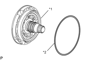
*1 Oil Pump Assembly *2 Oil Pump O-ring Coat a new oil pump O-ring with ATF and install it to the oil pump assembly.
-
Set the oil pump assembly on the input shaft, and align the bolt holes of the oil pump assembly with the automatic transmission case sub-assembly.
-
Temporarily install the oil pump assembly to the automatic transmission case sub-assembly.
-
Install the oil pump assembly with the 11 bolts.
- Torque:
- 21.1 N*m { 215 kgf*cm, 16 ft.*lbf }
Note
-
Make sure to apply seal packing to the flanges of the bolts.
Seal Packing Toyota Genuine Seal Packing 1281, Three Bond 1281 or equivalent -
Do not allow seal packing to contact the threads of the bolts.
-
Make sure the bolts and contact surface of the oil pump assembly are free of oil.
-
-
INSPECT INDIVIDUAL PISTON OPERATION
-
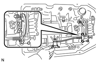
INSTALL MANUAL VALVE LEVER SHAFT OIL SEAL
-
Using SST and a hammer, install a new manual valve lever shaft oil seal to the automatic transmission case sub-assembly.
- SST
- 09350-30020 ( 09350-07110 )
Standard Depth -0.3 to 0.3 mm (-0.0118 to 0.0118 in.) -
Coat the lip of the manual valve lever shaft oil seal with MP grease.
-
-
INSTALL MANUAL VALVE LEVER SUB-ASSEMBLY
-
*1 Spacer Install a new spacer to the manual valve lever sub-assembly.
-
Install the manual valve lever shaft to the manual valve lever sub-assembly and automatic transmission case sub-assembly.
-
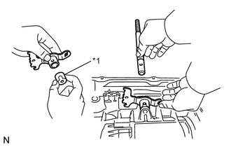
*1 Spring Pin Using a hammer, install a new spring pin to the manual valve lever shaft.
-
Turn the spacer and manual valve lever shaft to align the smaller hole on the spacer with the indent on the manual valve lever sub-assembly.
-
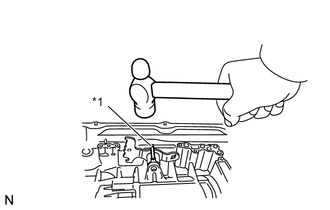
Using a 3 mm pin punch and a hammer, stake the spacer.
-
Check that the spacer does not turn.
-
-
INSTALL PARKING LOCK PAWL SHAFT
-
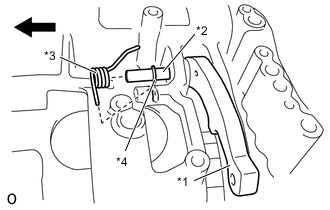
*1 Parking Lock Pawl *2 Parking Lock Pawl Shaft *3 Spring *4 E-ring Front Side Install the E-ring to the parking lock pawl shaft.
-
Install the parking lock pawl, parking lock pawl shaft and spring to the automatic transmission case sub-assembly.
-
-
INSTALL PARKING LOCK ROD SUB-ASSEMBLY
-
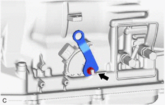
*1 Manual Valve Lever Sub-assembly *2 Parking Lock Rod Sub-assembly Connect the parking lock rod sub-assembly to the manual valve lever sub-assembly.
-
-
INSTALL PARKING LOCK PAWL BRACKET
-
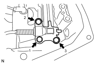
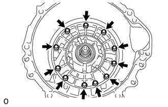
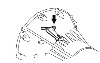
Install the parking lock pawl bracket to the automatic transmission case sub-assembly with the 3 bolts, in several steps in the order shown in the illustration.
- Torque:
- 18 N*m { 184 kgf*cm, 13 ft.*lbf }
-
Move the manual valve lever sub-assembly to the P position, and check the output shaft is locked by the parking lock pawl.
-
-
INSTALL AUTOMATIC TRANSMISSION CASE PLUG
-
Coat a new O-ring with ATF and install it to the automatic transmission case plug.
-
Using a 17 mm hexagon socket wrench, install the automatic transmission case plug to the automatic transmission case sub-assembly.
- Torque:
- 80 N*m { 816 kgf*cm, 59 ft.*lbf }
-
-
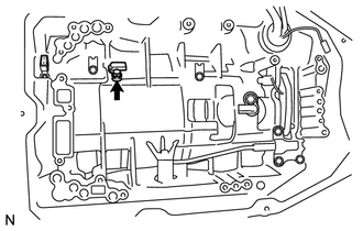
INSTALL TRANSMISSION REVOLUTION SENSOR (NT)
-
Coat the O-ring with ATF.
-
Using a T30 ''TORX'' socket wrench, install the transmission revolution sensor (NT) to the automatic transmission case sub-assembly with the bolt.
- Torque:
- 6.8 N*m { 69 kgf*cm, 60 in.*lbf }
-
-
INSTALL TRANSMISSION REVOLUTION SENSOR (SP2)
-
Install the transmission revolution sensor (SP2) to the automatic transmission case sub-assembly with the bolt.
- Torque:
- 5.4 N*m { 55 kgf*cm, 48 in.*lbf }
-
-
INSTALL TRANSMISSION REVOLUTION SENSOR (NC3)
-
Install the transmission revolution sensor (NC3) to the automatic transmission case sub-assembly with the bolt.
- Torque:
- 5.4 N*m { 55 kgf*cm, 48 in.*lbf }
-
-
INSTALL TRANSMISSION WIRE
-
Install the 2 valve body wire harness clamps to the automatic transmission case sub-assembly with the 2 bolts.
- Torque:
- 5.4 N*m { 55 kgf*cm, 48 in.*lbf }
-
Coat a new O-ring with ATF.
-
Install the transmission wire to the automatic transmission case sub-assembly with the bolt.
- Torque:
- 5.4 N*m { 55 kgf*cm, 48 in.*lbf }
-
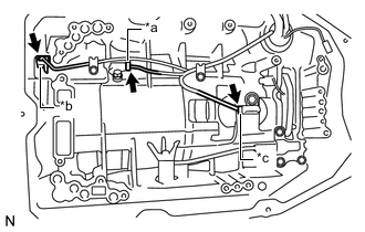
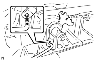
*1 Transmission Revolution Sensor (NC3) Connector *2 Transmission Revolution Sensor (NT) Connector *3 Transmission Revolution Sensor (SP2) Connector Connect the transmission revolution sensor (SP2) connector.
-
Connect the transmission revolution sensor (NT) connector.
-
Connect the transmission revolution sensor (NC3) connector.
-
-
INSTALL TRANSMISSION VALVE BODY ASSEMBLY
-
INSTALL VALVE BODY OIL STRAINER ASSEMBLY
-
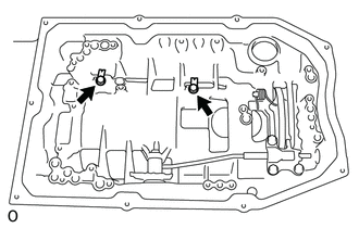
INSTALL AUTOMATIC TRANSMISSION OIL PAN SUB-ASSEMBLY
-
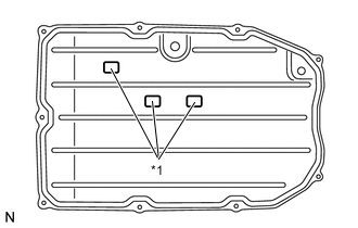
*1 Transmission Oil Cleaner Magnet Install the 3 transmission oil cleaner magnets to the automatic transmission oil pan sub-assembly as shown in the illustration.
-
Install a new automatic transmission oil pan gasket to the automatic transmission oil pan sub-assembly.
-
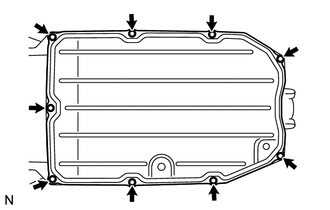
Install the automatic transmission oil pan sub-assembly with automatic transmission oil pan gasket to the automatic transmission case sub-assembly with the 9 bolts.
- Torque:
- 7.4 N*m { 75 kgf*cm, 65 in.*lbf }
Note
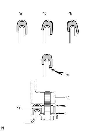
*1 Sleeve *2 Automatic Transmission Case Sub-assembly *a Correct *b Incorrect *c Protrusion
-
Make sure that automatic transmission oil pan gasket seal surface and automatic transmission oil pan sub-assembly contact surface are free of oil and foreign matter.
-
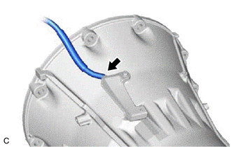
Install the automatic transmission oil pan gasket so that there is no slack in the automatic transmission oil pan gasket, and the entire seal surface is level.
-
Make sure that the 9 protrusions are properly engaged to the automatic transmission oil pan sub-assembly.
-
When installing the automatic transmission oil pan sub-assembly, make sure that the automatic transmission oil pan gasket is not pinched between sleeve and the seal surface of the automatic transmission case sub-assembly.
-
-
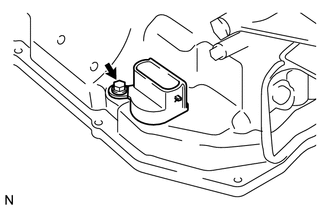
INSTALL AUTOMATIC TRANSMISSION BREATHER TUBE
-
Install a new O-ring to the automatic transmission breather tube.
-
Install the automatic transmission breather tube to the automatic transmission case sub-assembly with the bolt.
- Torque:
- 5.4 N*m { 55 kgf*cm, 48 in.*lbf }
-
Install the breather plug hose to the automatic transmission breather tube.
-
-
INSTALL OIL COOLER TUBE UNION
-
Coat 2 new O-rings with ATF and install them to the 2 oil cooler tube unions.
-
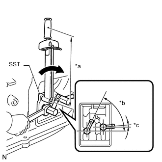
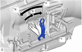
*a Torque Wrench Fulcrum Length *b 63° to 67° *c 3° to 7° Using SST, install the 2 oil cooler tube unions to automatic transmission assembly.
- SST
- 09268-78010
- Torque:
- Specified tightening torque
- 31.1 N*m { 317 kgf*cm, 23 ft.*lbf }
Tech Tips
-
Calculate the torque wrench reading when changing the fulcrum length of the torque wrench.
-
When using SST (fulcrum length of 34 mm (1.34 in.)) + torque wrench (fulcrum length of 180 mm (7.09 in.)):
26.2 N*m (267 kgf*cm, 19 ft.*lbf)
-
-
INSTALL PARK/NEUTRAL POSITION SWITCH ASSEMBLY
Tech Tips
Make sure that the manual valve lever shaft has not been rotated prior to installing the park/neutral position switch assembly as the detent spring may become detached from the manual valve lever shaft.
-
Clean the bolt and bolt hole.
-
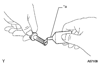
*a Adhesive 1344 Apply adhesive to 2 or 3 threads on the end of the bolt.
Adhesive Toyota Genuine Adhesive 1344, Three Bond 1344 or equivalent Note
Install the bolt within 3 minutes of applying adhesive.
-
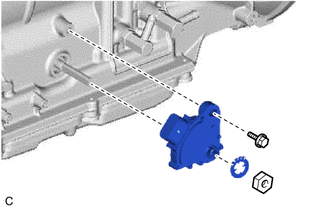
Temporarily install the park/neutral position switch assembly to the automatic transmission case sub-assembly with the bolt.
-
Install a new lock washer and the nut to the park/neutral position switch assembly.
- Torque:
- 6.9 N*m { 70 kgf*cm, 61 in.*lbf }
-
Temporarily install the transmission control shaft lever RH to the manual valve lever shaft with the spring washer and nut.
-
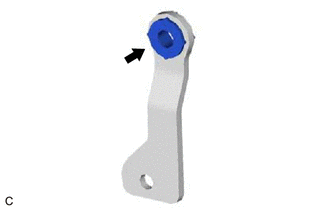
*1 Transmission Control Shaft Lever RH *a P *b R *c N Turn the transmission control shaft lever RH counterclockwise until it stops, then turn it clockwise 2 notches.
-
Remove the nut, spring washer and transmission control shaft lever RH from the manual valve lever shaft.
-
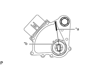
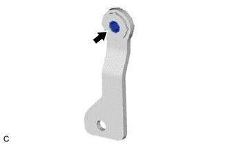
*a Neutral Basic Line *b Groove Align the neutral basic line with the groove as shown in the illustration.
-
Hold the park/neutral position switch assembly in that position and tighten the bolt.
- Torque:
- 12.8 N*m { 131 kgf*cm, 9 ft.*lbf }
-
Using a screwdriver, bend up the tabs of the lock washer.
-
-
INSTALL WIRE HARNESS CLAMP BRACKET
-
*1 Wire Harness Clamp Bracket Install the 2 wire harness clamp brackets to the automatic transmission case sub-assembly with the 2 bolts.
- Torque:
- 10 N*m { 102 kgf*cm, 7 ft.*lbf }
-
-
INSTALL TRANSMISSION CONTROL SHAFT LEVER RH
-
Install the transmission control shaft lever RH to the manual valve lever shaft with the spring washer and nut.
- Torque:
- 15.7 N*m { 160 kgf*cm, 12 ft.*lbf }
-
Install the grommet to the transmission control shaft lever RH.
-
Install the manual valve lever shaft spacer to the transmission control shaft lever RH.
-