COMBINATION SWITCH INSPECTION
PROCEDURE
-
INSPECT COMBINATION SWITCH ASSEMBLY
-
Inspect the ECO drive mode switch:
-
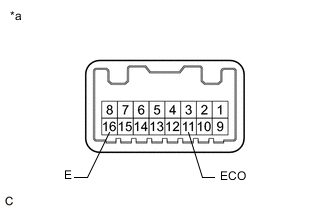
*a Component without harness connected
(Combination Switch Assembly)
Measure the resistance according to the value(s) in the table below.
Standard Resistance Tester Connection Condition Specified Condition 11 (ECO) - 16 (E) Combination switch assembly knob turned and held at ECO position Below 50 Ω Combination switch assembly knob not turned to ECO position 10 kΩ or higher If the result is not as specified, replace the combination switch assembly.
-
-
Inspect NORMAL or CUSTOMIZE mode switch:
-
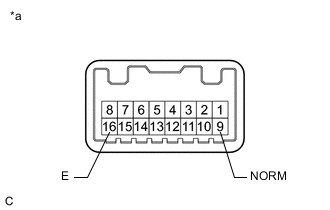
*a Component without harness connected
(Combination Switch Assembly)
Measure the resistance according to the value(s) in the table below.
Standard Resistance Tester Connection Condition Specified Condition 9 (NORM) - 16 (E) Combination switch assembly knob pushed and held Below 50 Ω Combination switch assembly knob not pushed 10 kΩ or higher If the result is not as specified, replace the combination switch assembly.
-
-
Inspect the SPORT or SPORT S/S+ mode switch:
-
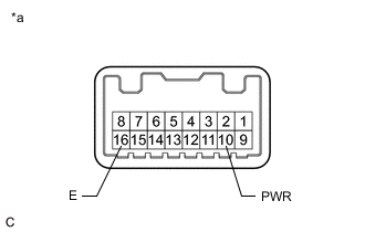
*a Component without harness connected
(Combination Switch Assembly)
Measure the resistance according to the value(s) in the table below.
Standard Resistance Tester Connection Condition Specified Condition 10 (PWR) - 16 (E) Combination switch assembly knob turned and held at SPORT or SPORT S/S+ position Below 50 Ω Combination switch assembly knob not turned to SPORT or SPORT S/S+ position 10 kΩ or higher If the result is not as specified, replace the combination switch assembly.
-
-
Inspect the SNOW mode switch:
-
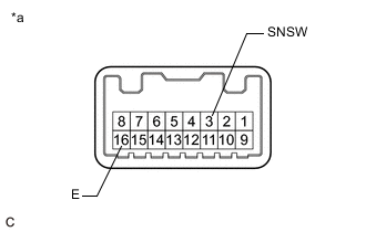
*a Component without harness connected
(Combination Switch Assembly)
Measure the resistance according to the value(s) in the table below.
Standard Resistance Tester Connection Condition Specified Condition 3 (SNSW) - 16 (E) SNOW mode switch pushed and held Below 50 Ω SNOW mode switch not pushed 10 kΩ or higher If the result is not as specified, replace the combination switch assembly.
-
-
Inspect the VSC off mode switch:
-
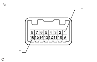
*a Component without harness connected
(Combination Switch Assembly)
Measure the resistance according to the value(s) in the table below.
Standard Resistance Tester Connection Condition Specified Condition 1 (+) - 16 (E) VSC OFF mode switch pushed and held Below 50 Ω VSC OFF mode switch not pushed 10 kΩ or higher If the result is not as specified, replace the combination switch assembly.
-
-
Inspect the TVD mode switch:
-
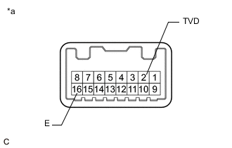
*a Component without harness connected
(Combination Switch Assembly)
Measure the resistance according to the value(s) in the table below.
Standard Resistance Tester Connection Condition Specified Condition 2 (TVD) - 16 (E) TVD mode switch pushed and held Below 50 Ω TVD mode switch not pushed 10 kΩ or higher If the result is not as specified, replace the combination switch assembly.
-
-
Check the illumination (w/ Torque Vectoring Differential Carrier Assembly):
-
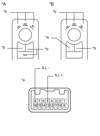
*A w/ Snow Switch *B w/o Snow Switch *a Component without harness connected
(Combination Switch Assembly)
*b Combination Switch Assembly Illumination Apply battery voltage to the combination switch assembly and check that the combination switch assembly illuminates.
Standard Measurement Condition Specified Condition Battery positive (+) → 5 (ILL+) Battery negative (-) → 8 (ILL-) Illuminates If the result is not as specified, replace the combination switch assembly.
-
-
Check the illumination (w/o Torque Vectoring Differential Carrier Assembly):
-
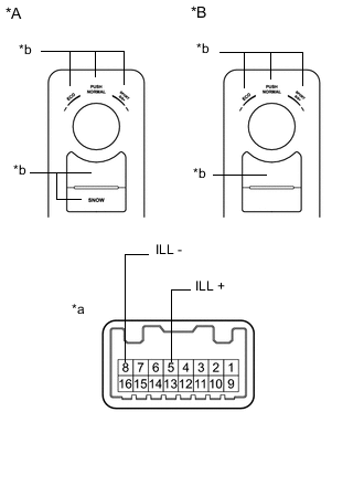
*A w/ Snow Switch *B w/o Snow Switch *a Component without harness connected
(Combination Switch Assembly)
*b Combination Switch Assembly Illumination Apply battery voltage to the combination switch assembly and check that the combination switch assembly illuminates.
Standard Measurement Condition Specified Condition Battery positive (+) → 5 (ILL+) Battery negative (-) → 8 (ILL-) Illuminates If the result is not as specified, replace the combination switch assembly.
-
-