PROCEDURE
- Click here
INSTALL TRANSMISSION VALVE BODY ASSEMBLY
-
Install the spring and check ball body to the automatic transmission case sub-assembly.
-
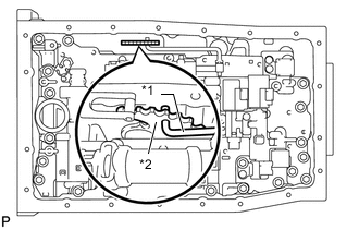
*1 Manual Valve Connecting Rod *2 Manual Valve Lever Sub-assembly Connect the manual valve connecting rod to the manual valve lever sub-assembly.
-
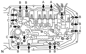
Install the transmission valve body assembly to the automatic transmission case sub-assembly with the 17 bolts.
11 N*m 112 kgf*cm 8 ft.*lbf Bolt Length Bolt (A) 21 mm (0.827 in.) Bolt (B) 31 mm (1.22 in.) Bolt (C) 64 mm (2.52 in.) -
Install the detent spring and detent spring cover with the bolt.
10 N*m 102 kgf*cm 7 ft.*lbf -
Connect the 9 shift solenoid valve connectors.
-
Connect the oil pressure switch connector.
-
Coat the O-ring with ATF.
-
Connect the ATF temperature sensor and install the lock plate with the bolt.
10 N*m 102 kgf*cm 7 ft.*lbf
-
- Click here
INSTALL VALVE BODY OIL STRAINER ASSEMBLY
-
Coat a new O-ring with ATF and install it to the valve body oil strainer assembly.
Note:Ensure that the O-ring is not twisted or pinched.
-
Install the valve body oil strainer assembly to the transmission valve body assembly with the 4 bolts.
10 N*m 102 kgf*cm 7 ft.*lbf
-
- Click here
INSTALL AUTOMATIC TRANSMISSION OIL PAN SUB-ASSEMBLY
-
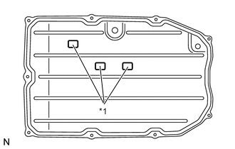
*1 Transmission Oil Cleaner Magnet Install the 3 transmission oil cleaner magnets to the automatic transmission oil pan sub-assembly as shown in the illustration.
-
Install a new automatic transmission oil pan gasket to the automatic transmission oil pan sub-assembly.
-
Install the automatic transmission oil pan sub-assembly with automatic transmission oil pan gasket to the automatic transmission case sub-assembly with the 9 bolts.
7.4 N*m 75 kgf*cm 65 in.*lbf Note: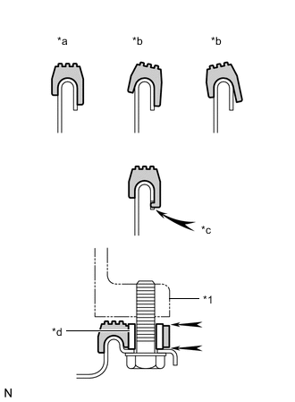
*1 Automatic Transmission Case Sub-assembly *a Correct *b Incorrect *c Protrusion *d Sleeve
-
Make sure that automatic transmission oil pan gasket seal surface and automatic transmission oil pan sub-assembly contact surface are free of oil and foreign matter.
-
Install the automatic transmission oil pan gasket so that there is no slack in the automatic transmission oil pan gasket, and the entire seal surface is level.
-
Make sure that the 9 protrusions are properly engaged to the automatic transmission oil pan sub-assembly.
-
When installing the automatic transmission oil pan sub-assembly, make sure that the automatic transmission oil pan gasket is not pinched between a sleeve and the seal surface of the automatic transmission case sub-assembly.
-
-
- Click here
INSTALL NO. 1 EXHAUST PIPE SUPPORT BRACKET SUB-ASSEMBLY
-
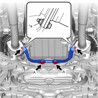
*a Nut Install the No. 1 exhaust pipe support bracket sub-assembly to the exhaust manifold sub-assembly LH (TWC: Front Catalyst), exhaust manifold sub-assembly RH (TWC: Front Catalyst) and automatic transmission assembly with the 2 bolts (A), 2 new bolts (B) and 2 new nuts.
for Bolt (A) 43 N*m 438 kgf*cm 32 ft.*lbf for Bolt (B) 39 N*m 398 kgf*cm 29 ft.*lbf Tip:Tighten the bolt (B) while holding the nut.
-
- Click here
ADD AUTOMATIC TRANSMISSION FLUID
- Click here
RESET MEMORY