AUTOMATIC TRANSMISSION SYSTEM, Diagnostic DTC:P0872
| DTC Code | DTC Name |
|---|---|
| P0872 | Transmission Fluid Pressure Sensor / Switch "C" Circuit Low |
DESCRIPTION
The oil pressure switch, which is built into the valve body, detects the fluid pressure of the SL1 fluid pressure circuit.
| DTC No. | Detection Item | DTC Detection Condition | Trouble Area | MIL | Memory |
|---|---|---|---|---|---|
| P0872 | Transmission Fluid Pressure Sensor / Switch "C" Circuit Low | 1. Diagnosis Condition 2. Malfunction Status 3. Malfunction Time 4. Other
|
|
Comes on | DTC stored |
WIRING DIAGRAM
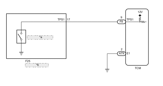
| *a | Oil Pressure Switch |
| *b | Transmission Wire |
CAUTION / NOTICE / HINT
Note
Perform registration and/or initialization when parts related to the automatic transmission are replaced.
Tech Tips
After the repair, clear the DTCs and perform the following procedure to check that DTCs are not output.
-
Perform the D Position Shift Test in Road Test.
-
Turn the engine switch off.
-
Perform step (1) again.
-
Check for DTCs again.
PROCEDURE
-
READ VALUE USING GTS (TPS 1 SWITCH SIGNAL)
-
Connect the GTS to the DLC3.
-
Turn the engine switch on (IG).
-
Turn the GTS on.
-
Enter the following menus: Powertrain / ECT / Active Test / Control the Shift Position / Data List / TPS 1 Switch.
Powertrain > ECT > Active TestTester Display Measurement Item Control Range Diagnostic Note Control the Shift Position Operates the shift solenoid valves to allow gears to be selected manually.
-
Press "→" button: Upshift occurs
-
Press "←" button: Downshift occurs
Possible to check operation of the shift solenoid valves.
[Vehicle Condition]
Vehicle speed: 50 km/h (31 mph) or less
Powertrain > ECT > Data ListTester Display Measurement Item Range Normal Condition Diagnostic Note TPS 1 Switch Oil pressure switch status ON or OFF
-
ON: Gear is 1st to 5th
-
OFF: Gear is 6th to 8th; or shift lever is in P, N or R
-
Powertrain > ECT > Active TestActive Test Display Control the Shift Position Data List Display TPS 1 Switch Result Result Proceed to When the vehicle is being driven in a gear position between 1st and 5th, ON is displayed for TPS 1 Switch on the Data List. A When the vehicle is being driven in a gear position between 1st and 5th, OFF is displayed for TPS 1 Switch on the Data List. B -
B 
CHECK HARNESS AND CONNECTOR (TRANSMISSION WIRE - TCM) Click here
A 
-
-
REPLACE TCM
-
Replace the TCM.
Result Proceed to NEXT
NEXT 
PERFORM A/T CODE REGISTRATION Click here
-
-
CHECK HARNESS AND CONNECTOR (TRANSMISSION WIRE - TCM)
-
Disconnect the F25 transmission wire connector.
-
Disconnect the F8 TCM connector.
-
Measure the resistance according to the value(s) in the table below.
Standard Resistance Tester Connection Condition Specified Condition F25-17 (TPS1) - F8-9 (TPS1) Always Below 1 Ω F25-17 (TPS1) or F8-9 (TPS1) - Body ground Always 10 kΩ or higher Result Proceed to OK NG
NG
REPAIR OR REPLACE HARNESS OR CONNECTOR (TRANSMISSION WIRE - TCM)
OK
-
-
INSPECT TRANSMISSION WIRE (OIL PRESSURE SWITCH)
-
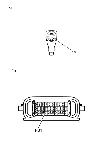
*a Front view of wire harness connector
(to Oil Pressure Switch Connector)
*b Component without harness connected
(Transmission Wire)
*c Connector Disconnect the oil pressure switch connector.
-
Disconnect the F25 transmission wire connector.
-
Measure the resistance according to the value(s) in the table below.
Standard Resistance Tester Connection Condition Specified Condition Oil pressure switch connector - 17 (TPS1) Always Below 1 Ω Oil pressure switch connector or 17 (TPS1) - Body ground Always 10 kΩ or higher Result Proceed to OK NG
OK
REPLACE OIL PRESSURE SWITCH Click here
NG
REPAIR OR REPLACE TRANSMISSION WIRE Click here
-