| DTC Code | DTC Name |
|---|---|
| P2769 | Short in Torque Converter Clutch Solenoid Circuit (Shift Solenoid Valve SL) |
| P2770 | Open in Torque Converter Clutch Solenoid Circuit (Shift Solenoid Valve SL) |
DESCRIPTION
By turning the shift solenoid valve SL ON or OFF, the TCM controls the fluid pressure to the lock-up relay valve, performing lock-up control.
| DTC No. | Detection Item | DTC Detection Condition | Trouble Area | MIL | Memory |
|---|---|---|---|---|---|
| P2769 | Short in Torque Converter Clutch Solenoid Circuit (Shift Solenoid Valve SL) | 1. Diagnosis Condition 2. Malfunction Status 3. Malfunction Time 4. Other
|
|
Comes on | DTC stored |
| P2770 | Open in Torque Converter Clutch Solenoid Circuit (Shift Solenoid Valve SL) | 1. Diagnosis Condition 2. Malfunction Status 3. Malfunction Time 4. Other
|
|
Comes on | DTC stored |
Fail-safe function:
If the TCM detects a malfunction, it turns the shift solenoid valve SL OFF.
MONITOR DESCRIPTION
Based on the signals from the throttle position sensor, the air flow meter and the crankshaft position sensor, the TCM sends a signal to the solenoid valve SL to regulate the hydraulic pressure and provide smooth torque converter assembly engagement. The shift solenoid valve SL responds to commands from the TCM and controls the lock-up relay valve to perform the torque-converter lock-up function. If the TCM detects an open or short circuit in the shift solenoid valve SL circuit, it will illuminate the MIL and store a DTC.
CAUTION / NOTICE / HINT
Perform registration and/or initialization when parts related to the automatic transmission are replaced.
After the repair, clear the DTCs and perform the following procedure to check that DTCs are not output.
-
Perform the Lock-up Function in Road Test.
-
Turn the engine switch off.
-
Perform step (1) again.
-
Check for DTCs again.
PROCEDURE
- Click here
CHECK HARNESS AND CONNECTOR (TRANSMISSION WIRE (SHIFT SOLENOID VALVE SL) - TCM)
-
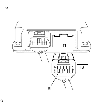
*a Rear view of wire harness connector
(to TCM)
Disconnect the F8 TCM connector.
-
Measure the resistance according to the value(s) in the table below.
Standard Resistance Tester Connection Condition Specified Condition F8-24 (SL) - Body ground 20°C (68°F) 11 to 15 Ω Result Proceed to OK NG
- OKClick here
- NGClick here
-
- Click here
REPLACE TCM
-
Replace the TCM.
Result Proceed to NEXT
- NEXT
PERFORM A/T CODE REGISTRATIONClick here
-
- Click here
CHECK HARNESS AND CONNECTOR (TRANSMISSION WIRE - TCM)
-
Disconnect the F25 transmission wire connector.
-
Disconnect the F8 TCM connector.
-
Measure the resistance according to the value(s) in the table below.
Standard Resistance Tester Connection Condition Specified Condition F25-7 (SL) - F8-24 (SL) Always Below 1 Ω F25-7 (SL) or F8-24 (SL) - Body ground Always 10 kΩ or higher Result Proceed to OK NG
- OKClick here
- NG
REPAIR OR REPLACE HARNESS OR CONNECTOR (TRANSMISSION WIRE - TCM)
-
- Click here
INSPECT SHIFT SOLENOID VALVE SL
-
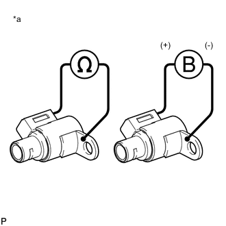
*a Shift Solenoid Valve SL Remove the shift solenoid valve SL.
-
Measure the resistance according to the value(s) in the table below.
Standard Resistance Tester Connection Condition Specified Condition Terminal of shift solenoid valve SL connector - Shift solenoid valve SL Body 20°C (68°F) 11 to 15 Ω -
Connect a positive (+) lead from the battery to the terminal of the solenoid valve connector, and a negative (-) lead to the solenoid body. Check that the valve moves and makes an operating sound.
OK Valve moves and makes an operating sound. Result Proceed to OK NG
- OK
REPAIR OR REPLACE TRANSMISSION WIREClick here
- NG
REPLACE SHIFT SOLENOID VALVE SLClick here
-