LANE DEPARTURE ALERT SYSTEM TERMINALS OF ECU
-
CHECK LANE DEPARTURE WARNING CAMERA

Terminal No. (Symbol) Wiring Color Terminal Description Condition Specified Condition W9-4 (LKSW) - W9-11 (GND)* R - BR Lane departure alert main switch (steering pad switch assembly) signal Engine switch on (IG), lane departure alert main switch (steering pad switch assembly) off 1 MΩ or higher W9-4 (LKSW) - W9-11 (GND)* R - BR Lane departure alert main switch (steering pad switch assembly) signal Engine switch on (IG), lane departure alert main switch (steering pad switch assembly) on 228 to 252 Ω W9-6 (CA1P) - W9-11 (GND) R - BR CAN communication signal Engine switch on (IG) Pulse generation
(Waveform 1)
W9-7 (IGB) - W9-11 (GND) V - BR Power source Engine switch on (IG) 11 to 14 V W9-11 (GND) - Body ground BR - Body ground Ground Always Below 1 Ω W9-12 (CA1N) - W9-11 (GND) B - BR CAN communication signal Engine switch on (IG) Pulse generation
(Waveform 1)
-
*: w/o Dynamic Radar Cruise Control System
If the result is not as specified, there may be a malfunction on the wire harness side.
Tech Tips
Oscilloscope waveform samples are provided here for reference only. Noise and fluctuating waveforms have been omitted.
-
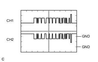
Waveform 1 (CAN communication signal)
Item Content Terminal Name CH1: W9-6 (CA1P) - W9-11 (GND)
CH2: W9-12 (CA1N) - W9-11 (GND)
Tester Range 1 V/DIV., 50 μs./DIV. Condition Engine switch on (IG) Tech Tips
The waveform will vary depending on the content of the digital communication (digital signal).
-
-
CHECK DRIVING SUPPORT ECU ASSEMBLY (w/ Dynamic Radar Cruise Control System)

Note
Do not apply excessive force to the connector. If a force of 10 kg or more is applied, the connector may brake.
Terminal No. (Symbol) Wiring Color Terminal Description Condition Specified Condition Q1-6 (SPSW) - Q1-25 (GND) W - BR Lane departure alert main switch (steering pad switch assembly) signal Engine switch on (IG), lane departure alert main switch (steering pad switch assembly) off 1 MΩ or higher Q1-6 (SPSW) - Q1-25 (GND) W - BR Lane departure alert main switch (steering pad switch assembly) signal Engine switch on (IG), lane departure alert main switch (steering pad switch assembly) on 228 to 252 Ω Q1-17 (CA2L) - Q1-25 (GND) B - BR CAN communication signal Engine switch on (IG) Pulse generation
(Waveform 1)
Q1-18 (CA1N) - Q1-25 (GND) G - BR CAN communication signal Engine switch on (IG) Pulse generation
(Waveform 2)
Q1-25 (GND) - Body ground BR - Body ground Ground Always Below 1 Ω Q1-27 (STP-) - Q1-25 (GND) R - BR Stop light switch assembly signal Brake pedal depressed Below 1.5 V Q1-27 (STP-) - Q1-25 (GND) R - BR Stop light switch assembly signal Brake pedal released 7.5 to 14 V Q1-28 (ST1-) - Q1-25 (GND) P - BR Stop light switch assembly signal (opposite to STP terminal) Engine switch on (IG), Brake pedal depressed Below 1.5 V Q1-28 (ST1-) - Q1-25 (GND) P - BR Stop light switch assembly signal (opposite to STP terminal) Engine switch on (IG), Brake pedal released 7.5 to 14 V Q1-30 (B) - Q1-25 (GND) B - BR Power source Engine switch on (IG) 11 to 14 V Q1-39 (CA2H) - Q1-25 (GND) G - BR CAN communication signal Engine switch on (IG) Pulse generation
(Waveform 1)
Q1-40 (CA1P) - Q1-25 (GND) B - BR CAN communication signal Engine switch on (IG) Pulse generation
(Waveform 2)
If the result is not as specified, there may be a malfunction on the wire harness side.
Tech Tips
Oscilloscope waveform samples are provided here for reference only. Noise and fluctuating waveforms have been omitted.
-
Waveform 1 (CAN communication signal)
Item Content Terminal Name CH1: Q1-39 (CA2H) - Q1-25 (GND)
CH2: Q1-17 (CA2L) - Q1-25 (GND)
Tester Range 1 V/DIV., 50 μs./DIV. Condition Engine switch on (IG) Tech Tips
The waveform will vary depending on the content of the digital communication (digital signal).
-
Waveform 2 (CAN communication signal)
Item Content Terminal Name CH1: Q1-40 (CA1P) - Q1-25 (GND)
CH2: Q1-18 (CA1N) - Q1-25 (GND)
Tester Range 1 V/DIV., 50 μs./DIV. Condition Engine switch on (IG) Tech Tips
The waveform will vary depending on the content of the digital communication (digital signal).
-