PROCEDURE
- Click here
INSTALL ENGINE WATER PUMP ASSEMBLY
-
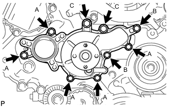
Install a new water pump gasket and the engine water pump assembly with the 9 bolts.
Bolt (A) 20 N*m 204 kgf*cm 15 ft.*lbf Bolt (B) 23 N*m 235 kgf*cm 17 ft.*lbf Bolt (C) 47 N*m 479 kgf*cm 35 ft.*lbf
-
- Click here
INSTALL WATER PUMP PULLEY
-
Temporarily install the water pump pulley with the 4 bolts.
-
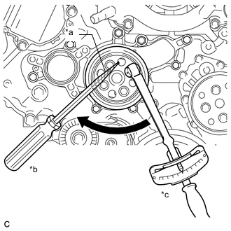
*a Protective Tape *b Hold *c Turn Using a screwdriver or equivalent, hold the water pump pulley and tighten the 4 bolts.
21 N*m 214 kgf*cm 15 ft.*lbf Tip:Tape the screwdriver tip before use.
-
- Click here
INSTALL WATER INLET HOUSING
-
Install the water inlet housing to the No. 3 water by-pass hose and slide the clip to secure it.
-
Install the water inlet hose to the water inlet housing and front water by-pass joint and slide the 2 clips to secure it.
-
Install a new No. 1 water inlet housing gasket to the engine water pump assembly.
-
Install the water inlet housing to the engine water pump assembly with the 3 bolts.
21 N*m 214 kgf*cm 15 ft.*lbf Note:Be careful not to allow the No. 1 water inlet housing gasket to get caught between the parts.
-
Connect the No. 5 water by-pass hose to the water inlet housing and slide the clip to secure it.
-
Connect the wire harness clamp bracket to the water inlet housing with the bolt.
12 N*m 122 kgf*cm 9 ft.*lbf
-
- Click here
CONNECT NO. 2 RADIATOR HOSE
- Click here
INSTALL V-RIBBED BELT
- Click here
INSTALL RADIATOR RESERVE TANK ASSEMBLY
- Click here
INSTALL AIR CLEANER CAP WITH AIR CLEANER HOSE
- Click here
CONNECT VENTILATION HOSE
- Click here
INSTALL V-BANK COVER SUB-ASSEMBLY
- Click here
ADD ENGINE COOLANT
- Click here
INSPECT FOR COOLANT LEAK
- Click here
INSTALL COOL AIR INTAKE DUCT SEAL
- Click here
INSTALL NO. 1 ENGINE UNDER COVER ASSEMBLY