PROCEDURE
- Click here
INSTALL TAIL EXHAUST PIPE BAFFLE SUB-ASSEMBLY
-
Set 4 new tail exhaust pipe baffle sub-assemblies to the tail exhaust pipe assembly and tail exhaust pipe LH.
-
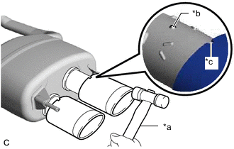
*a Plastic Hammer *b Protrusion *c Cutout Align the cutout of each tail exhaust pipe baffle sub-assembly with the protrusion of the tail exhaust pipe assembly and tail exhaust pipe LH as shown in the illustration.
-
Using a plastic hammer, uniformly tap each tail exhaust pipe baffle sub-assembly onto the tail exhaust pipe assembly and tail exhaust pipe LH.
-
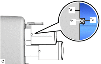
*a Tail Exhaust Pipe Baffle Sub-assembly Edge *b Protrusion *c Cutout Check that the cutout of each tail exhaust pipe baffle sub-assembly is aligned with the protrusion on the bottom of the tail exhaust pipe assembly and tail exhaust pipe LH as shown in the illustration.
Tip:Adjust the tail exhaust pipe baffle sub-assemblies if necessary.
-
- Click here
CONNECT TAIL EXHAUST PIPE LH
-
Connect the tail exhaust pipe LH to the 3 exhaust pipe supports.
Note:Protect the rear bumper assembly using protection material such as a piece of cloth to avoid damage by the tail exhaust pipe baffle sub-assemblies.
-
- Click here
CONNECT TAIL EXHAUST PIPE ASSEMBLY
-
Connect the tail exhaust pipe assembly to the 3 exhaust pipe supports.
Note:Protect the rear bumper assembly using protection material such as a piece of cloth to avoid damage by the tail exhaust pipe baffle sub-assemblies.
-
- Click here
INSTALL FRONT EXHAUST PIPE ASSEMBLY
-
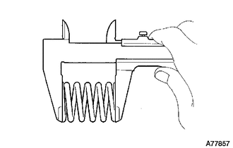
Using a vernier caliper, measure the free length of the compression springs.
Standard Length 40 mm (1.57 in.) Minimum Free Length 38.5 mm (1.52 in.) If the free length is less than the minimum, replace the compression spring.
-
Temporarily install 2 new gaskets to the front exhaust pipe assembly for tail exhaust pipe assembly and tail exhaust pipe LH side.
-
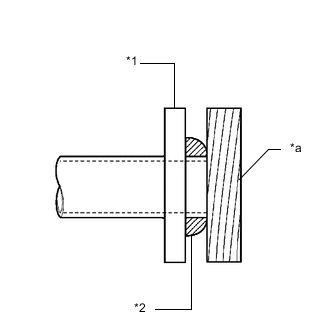
*1 Front Exhaust Pipe Assembly *2 Gasket *a Wooden Block Using a plastic hammer and wooden block, tap in each gaskets until its surface is flush with the front exhaust pipe assembly.
Note:
-
Be sure to install the gaskets in the correct direction.
-
Do not reuse the gaskets.
-
Do not damage the gaskets.
-
Do not push in the gaskets by using the exhaust pipes when connecting them.
-
-
Install 2 new gaskets to the front exhaust pipe assembly for exhaust manifold sub-assembly LH and exhaust manifold sub-assembly RH side.
-
Connect the front exhaust pipe assembly with 4 new nuts and 4 new bolts.
39 N*m 398 kgf*cm 29 ft.*lbf -
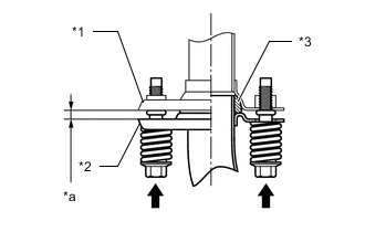
*1 Tail Exhaust Pipe Assembly or Tail Exhaust Pipe LH *2 Front Exhaust Pipe Assembly *3 Gasket *a Space between Flanges: 6.5 mm (0.256 in.) Install the front exhaust pipe assembly to the tail exhaust pipe assembly and tail exhaust pipe LH with the 4 bolts and 4 compression springs.
43 N*m 438 kgf*cm 32 ft.*lbf Tip:After installation, check that the space between the flanges of the front exhaust pipe assembly and tail exhaust pipe assembly and tail exhaust pipe LH is consistent front-to-rear and left-to-right.
-
- Click here
CONNECT HEATED OXYGEN SENSOR
Tip:Perform "Inspection After Repair" after replacing a heated oxygen sensor. (w/ Canister Pump Module)
-
for Bank 2:
-
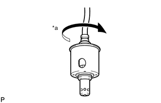
*a 4 Turns Before installing the heated oxygen sensor, twist the sensor wire counterclockwise 4 turns.
-
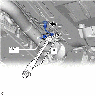
*a Torque Wrench Fulcrum Length Using SST, connect the heated oxygen sensor to the front exhaust pipe assembly.
09224-00012 Specified tightening torque 44 N*m 449 kgf*cm 32 ft.*lbf Note:Be careful not to drop the heated oxygen sensor.
Tip:
-
Calculate the torque wrench reading when changing the fulcrum length of the torque wrench.
Click here
-
When using SST (fulcrum length of 30 mm (1.18 in.)) + torque wrench (fulcrum length of 260 mm (10.2 in.)):
39 N*m (398 kgf*cm, 29 ft.*lbf)
-
-
Engage the heated oxygen sensor grommet to the vehicle body.
-
Install the bolt.
8.0 N*m 82 kgf*cm 71 in.*lbf
-
-
for Bank 1:
-
*a 4 Turns Before installing the heated oxygen sensor, twist the sensor wire counterclockwise 4 turns.
-
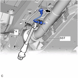
*a Torque Wrench Fulcrum Length Using SST, connect the heated oxygen sensor to the front exhaust pipe assembly.
09224-00012 Specified tightening torque 44 N*m 449 kgf*cm 32 ft.*lbf Note:Be careful not to drop the heated oxygen sensor.
Tip:
-
Calculate the torque wrench reading when changing the fulcrum length of the torque wrench.
-
When using SST (fulcrum length of 30 mm (1.18 in.)) + torque wrench (fulcrum length of 260 mm (10.2 in.)):
39 N*m (398 kgf*cm, 29 ft.*lbf)
-
-
Engage the heated oxygen sensor grommet to the vehicle body.
-
-
- Click here
INSTALL FRONT CENTER FLOOR BRACE
- Click here
INSTALL FRONT CENTER FLOOR COVER LH
- Click here
INSTALL FRONT CENTER FLOOR COVER RH
- Click here
INSPECT FOR EXHAUST GAS LEAK
If gas is leaking, tighten the areas necessary to stop the leak. Replace damaged parts as necessary.
-
Perform "Inspection After Repair" after repairing an exhaust gas leak.
-
w/ Canister Pump Module
-
w/o Canister Pump Module
-
-
- Click here
PERFORM INITIALIZATION (w/ Differential Pressure Sensor)
-
Perform "Inspection After Repair" after replacing a front exhaust pipe assembly.
-