PROCEDURE
- Click here
INSTALL EXHAUST MANIFOLD TO HEAD GASKET (for Bank 2)
-
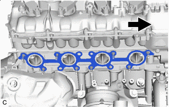

Front Install a new exhaust manifold to head gasket to the cylinder head sub-assembly as shown in the illustration.
-
- Click here
INSTALL EXHAUST MANIFOLD SUB-ASSEMBLY RH
-
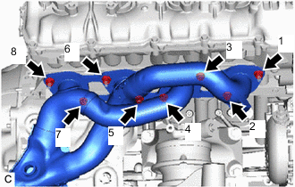
Temporarily install the exhaust manifold sub-assembly RH to the cylinder head sub-assembly with the 8 nuts.
-
Tighten the 8 nuts in the order shown in the illustration.
21 N*m 214 kgf*cm 15 ft.*lbf
-
- Click here
INSTALL NO. 1 EXHAUST MANIFOLD HEAT INSULATOR
-
Install the No. 1 exhaust manifold heat insulator to the exhaust manifold sub-assembly RH with the 3 bolts.
10 N*m 102 kgf*cm 7 ft.*lbf
-
- Click here
INSTALL ENGINE OIL LEVEL DIPSTICK GUIDE
-
Apply a light coat of engine oil to a new O-ring.
-
Install the O-ring to the engine oil level dipstick guide.
-
Install the engine oil level dipstick guide with the bolt.
10 N*m 102 kgf*cm 7 ft.*lbf
-
- Click here
INSTALL ENGINE OIL LEVEL DIPSTICK
-
Install the engine oil level dipstick to the engine oil level dipstick guide.
-
- Click here
INSTALL ENGINE UNDER COVER SUB-ASSEMBLY RH
- Click here
INSTALL EXHAUST MANIFOLD TO HEAD GASKET (for Bank 1)
-
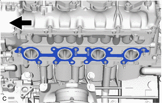
Front Install a new exhaust manifold to head gasket to the cylinder head sub-assembly as shown in the illustration.
-
- Click here
INSTALL EXHAUST MANIFOLD SUB-ASSEMBLY LH
-
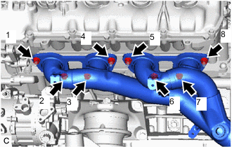
Temporarily install the exhaust manifold sub-assembly LH to the cylinder head sub-assembly with the 8 nuts.
-
Tighten the 8 nuts in the order shown in the illustration.
21 N*m 214 kgf*cm 15 ft.*lbf
-
- Click here
INSTALL NO. 2 EXHAUST MANIFOLD HEAT INSULATOR
-
Install the No. 2 exhaust manifold heat insulator to the exhaust manifold sub-assembly LH with the 3 bolts.
10 N*m 102 kgf*cm 7 ft.*lbf
-
- Click here
INSTALL ENGINE MOUNTING DAMPER
-
Install the engine mounting damper to the front No. 1 engine mount bracket with the bolt.
10 N*m 102 kgf*cm 7 ft.*lbf
-
- Click here
CONNECT NO. 2 VACUUM PIPE (w/ Differential Pressure Sensor)
-
Temporarily install the No. 2 vacuum pipe to the exhaust manifold sub-assembly LH.
-
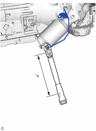
Connect the No. 2 vacuum pipe to the exhaust manifold sub-assembly LH with the bolt.
10 N*m 102 kgf*cm 7 ft.*lbf -
*a Torque Wrench Fulcrum Length Using a 14 mm union nut wrench, connect the No. 2 vacuum pipe to the exhaust manifold sub-assembly LH with the bolt.
Specified tightening torque 30 N*m 306 kgf*cm 22 ft.*lbf Tip:
-
Calculate the torque wrench reading when changing the fulcrum length of the torque wrench.
-
When using a 14 mm union nut wrench (fulcrum length of 25 mm (0.984 in.)) + torque wrench (fulcrum length of 180 mm (7.09 in.)):
26.3 N*m (268 kgf*cm, 19 ft.*lbf)
-
-
- Click here
CONNECT NO. 1 VACUUM PIPE (w/ Differential Pressure Sensor)
-
Temporarily install the No. 1 vacuum pipe to the exhaust manifold sub-assembly RH.
-
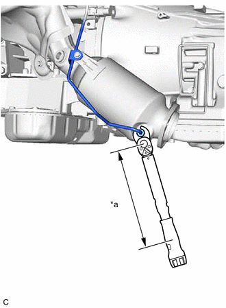
Connect the No. 1 vacuum pipe to the exhaust manifold sub-assembly RH with the bolt.
10 N*m 102 kgf*cm 7 ft.*lbf -
*a Torque Wrench Fulcrum Length Using a 14 mm union nut wrench, connect the No. 1 vacuum pipe to the exhaust manifold sub-assembly RH with the bolt.
Specified tightening torque 30 N*m 306 kgf*cm 22 ft.*lbf Tip:
-
Calculate the torque wrench reading when changing the fulcrum length of the torque wrench.
-
When using a 14 mm union nut wrench (fulcrum length of 25 mm (0.984 in.)) + torque wrench (fulcrum length of 180 mm (7.09 in.)):
26.3 N*m (268 kgf*cm, 19 ft.*lbf)
-
-
- Click here
INSTALL AIR FUEL RATIO SENSOR