DIFFERENTIAL PRESSURE SENSOR ON-VEHICLE INSPECTION

PROCEDURE
-
INSPECT DIFFERENTIAL PRESSURE SENSOR ASSEMBLY
-
Connect the GTS to the DLC3.
-
Turn the engine switch ON (IG).
-
Turn the GTS on.
-
Remove the V-bank cover sub-assembly.
-
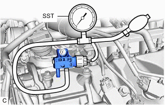
for Bank 1 side:
-
Enter the following menus: Powertrain / Engine / Data List / GPF Defferential Pressure Offset Bank1.
Powertrain > Engine > Data ListTester Display GPF Differential Pressure Offset Bank1 -
Slide the clip and disconnect the No. 2 vacuum transmitting hose assembly from the differential pressure sensor assembly.
-
Connect SST to the differential pressure sensor assembly.
- SST
- 09992-00242
-
Using SST, apply pressure to the differential pressure sensor assembly.
-
Check the pressure value of the differential pressure sensor assembly.
Standard GTS Display Condition Specified Condition GPF Defferential Pressure Offset Bank 1 Engine switch on (IG) When applying 20 kPa (2.9 psi): 20 kPa (2.9 psi)
When applying 40 kPa (5.8 psi): 40 kPa (5.8 psi)
Note
Perform the inspection within the range of 0 to 98 kPa (0 to 14.2 psi).
If the result is not as specified, replace the differential pressure sensor assembly.
-
Disconnect SST from the differential pressure sensor assembly.
-
Connect the No. 2 vacuum transmitting hose assembly to the differential pressure sensor assembly and slide the clip to secure it.
-
-
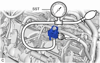
for Bank 2 side:
-
Enter the following menus: Powertrain / Engine / Data List / GPF Defferential Pressure Offset Bank2.
Powertrain > Engine > Data ListTester Display GPF Differential Pressure Offset Bank2 -
Slide the clip and disconnect the No. 1 vacuum transmitting hose assembly from the differential pressure sensor assembly.
-
Connect SST to the differential pressure sensor assembly.
- SST
- 09992-00242
-
Using SST, apply pressure to the differential pressure sensor assembly.
-
Check the pressure value of the differential pressure sensor assembly.
Standard GTS Display Condition Specified Condition GPF Defferential Pressure Offset Bank 2 Engine switch on (IG) When applying 20 kPa (2.9 psi): 20 kPa (2.9 psi)
When applying 40 kPa (5.8 psi): 40 kPa (5.8 psi)
Note
Perform the inspection within the range of 0 to 98 kPa (0 to 14.2 psi).
If the result is not as specified, replace the differential pressure sensor assembly.
-
Disconnect SST from the differential pressure sensor assembly.
-
Connect the No. 1 vacuum transmitting hose assembly to the differential pressure sensor assembly and slide the clip to secure it.
-
-
Install the V-bank cover sub-assembly.
-