FUEL TANK(w/o Canister Pump Module) INSTALLATION
PROCEDURE
-
INSTALL FUEL TANK PROTECTOR SUB-ASSEMBLY
-
Install the No. 2 fuel tank protector and No. 3 fuel tank protector to the fuel tank assembly.
-
Install the No. 1 fuel tank protector sub-assembly to the fuel tank assembly.
Tech Tips
Install the No. 1 fuel tank protector sub-assembly after installing the No. 2 fuel tank protector and No. 3 fuel tank protector.
-
-
INSTALL FUEL TANK CUSHION
-
Install the fuel tank bracket, 2 fuel tank cushions and fuel tank cushion set to the fuel tank assembly.
-
Install 5 new No. 6 fuel tank cushions to the fuel tank assembly.
-
-
INSTALL FUEL TANK MAIN TUBE SUB-ASSEMBLY
-
Engage the 2 clamps to install the No. 3 fuel tube clamp and No. 5 fuel tube clamp to the fuel tank assembly.
-
Engage the 2 clamps to install the fuel tank main tube sub-assembly to the fuel tank assembly.
-
-
INSTALL CHARCOAL CANISTER OUTLET HOSE
-
Engage the clamp to install the No. 4 fuel tube clamp to the fuel tank assembly.
-
Engage the clamp to install the charcoal canister outlet hose to the fuel tank assembly.
-
-
INSTALL NO. 1 FUEL EVAPORATION TUBE SUB-ASSEMBLY
-
Install the No. 1 fuel evaporation tube sub-assembly to the fuel tank assembly.
-
-
INSTALL FUEL TANK ASSEMBLY
-
Set the fuel tank assembly on an engine lifter with attachments.
Tech Tips
Using height adjustment attachments and plate lift attachments, keep the fuel tank assembly horizontal.
-
Using the engine lifter, slowly raise the fuel tank assembly, and then install the fuel tank assembly with the 2 nuts, 4 bolts and 2 No. 1 fuel tank band sub-assemblies.
- Torque:
- Nut
- 19.6 N*m { 200 kgf*cm, 14 ft.*lbf }
- Bolt
- 45 N*m { 459 kgf*cm, 33 ft.*lbf }
Note
-
Do not drop the fuel tank assembly.
-
When installing the fuel tank assembly, tilt it slightly to prevent it from interfering with the suspension arm or other surrounding parts.
-
-
INSTALL REAR BODY MOUNTING CUSHION SUB-ASSEMBLY LH
-
INSTALL REAR BODY MOUNTING CUSHION SUB-ASSEMBLY RH
-
INSTALL PARKING BRAKE CABLE ASSEMBLY
-
Install the No. 2 parking brake cable assembly and No. 3 parking brake cable assembly with the 2 bolts and 2 nuts.
- Torque:
- Bolt
- 19 N*m { 194 kgf*cm, 14 ft.*lbf }
- Nut
- 6.0 N*m { 61 kgf*cm, 53 in.*lbf }
-
Engage the 4 clamps.
-
-
CONNECT CHARCOAL CANISTER OUTLET HOSE
-
Connect the charcoal canister outlet hose to the No. 6 fuel tank breather tube.
-
-
CONNECT FUEL TANK BREATHER TUBE
-
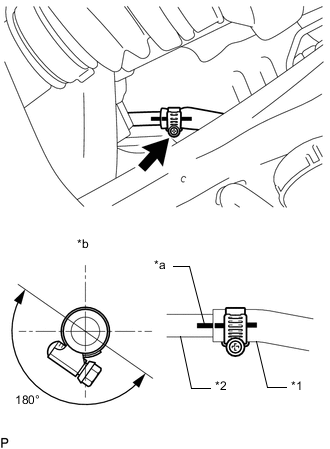
*1 Fuel Tank Breather Tube *2 Fuel Tank Breather Tube Connector *a Alignment Mark *b Top Align the alignment marks, connect the fuel tank breather tube to the fuel tank breather tube connector and tighten the clamp to secure it.
Tech Tips
Make sure the clamp bolt is within the area shown in the illustration.
-
Engage the 2 clamps to connect the fuel tank breather tube to the breather tube clamp and No. 2 evaporation vent tube clamp.
-
-
CONNECT FUEL TANK TO FILLER PIPE HOSE
-
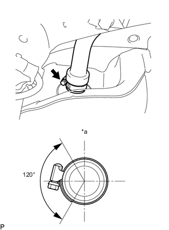
*a Top Connect the fuel tank to filler pipe hose to the fuel tank assembly and tighten the clamp to secure it.
Tech Tips
Make sure the clamp bolt is within the area shown in the illustration.
-
-
CONNECT NO. 1 FUEL EVAPORATION TUBE SUB-ASSEMBLY
-
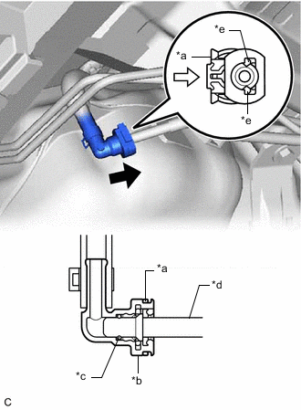
*a Retainer *b Fuel Tube Connector *c O-ring *d Fuel Pipe *e Claw 
Push 
Push in Connect the No. 1 fuel evaporation tube sub-assembly.
Note
Check if there is any damage or foreign matter on the connecting parts of the fuel lines.
-
Align the fuel tube connector with the fuel pipe, and push them together until the fuel tube connector makes a "click" sound. If it is difficult to push the fuel pipe into the fuel tube connector, apply a small amount of clean engine oil to the tip of the fuel pipe and reinsert it.
-
Connect the fuel lines and push in the retainer to engage the 2 claws. Check that the fuel pipe and fuel tube connector are securely connected by pulling on them.
-
-
-
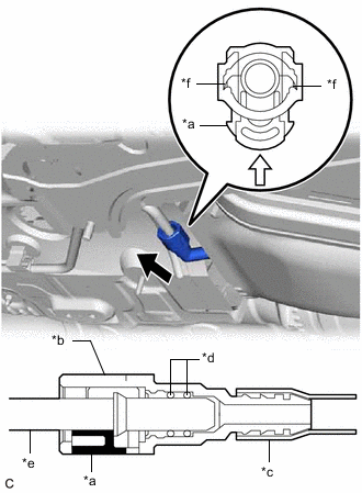
CONNECT FUEL TANK MAIN TUBE SUB-ASSEMBLY
-
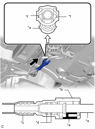
*a Retainer *b Fuel Tube Connector *c Nylon Tube *d O-ring *e Fuel Pipe *f Claw Push Push in Connect the fuel tank main tube sub-assembly on the RH side.
Note
Check if there is any damage or foreign matter on the connecting parts of the fuel lines.
-
Align the fuel tube connector with the fuel pipe, and push them together until the fuel tube connector makes a "click" sound. If it is difficult to push the fuel pipe into the fuel tube connector, apply a small amount of clean engine oil to the tip of the fuel pipe and reinsert it.
-
Connect the fuel lines and push in the retainer to engage the 2 claws. Check that the fuel pipe and fuel tube connector are securely connected by pulling on them.
-
-
*a Retainer *b Fuel Tube Connector *c Nylon Tube *d O-ring *e Fuel Pipe *f Claw Push Push in Connect the fuel tank main tube sub-assembly on the LH side.
Note
Check if there is any damage or foreign matter on the connecting parts of the fuel lines.
-
Align the fuel tube connector with the fuel pipe, and push them together until the fuel tube connector makes a "click" sound. If it is difficult to push the fuel pipe into the fuel tube connector, apply a small amount of clean engine oil to the tip of the fuel pipe and reinsert it.
-
Connect the fuel lines and push in the retainer to engage the 2 claws. Check that the fuel pipe and fuel tube connector are securely connected by pulling on them.
-
-
-
INSTALL PROPELLER SHAFT WITH CENTER BEARING ASSEMBLY
-
ADD FUEL
-
INSTALL FUEL TANK VENT TUBE ASSEMBLY
-
INSTALL FUEL SUCTION TUBE WITH PUMP AND GAUGE ASSEMBLY