VEHICLE STABILITY CONTROL SYSTEM, Diagnostic DTC:C1459

| DTC Code | DTC Name |
|---|---|
| C1459 | Vertical Acceleration Sensor |
DESCRIPTION
The roll rate and vertical acceleration sensor is built into the yaw rate sensor.
This DTC is output when the skid control ECU (brake actuator assembly) receives a malfunction signal from the roll rate and vertical acceleration sensor (yaw rate sensor).
Tech Tips
When a malfunction occurs in the communication line to the roll rate and vertical acceleration sensor (yaw rate sensor), U110F (Lost Communication With Roll Rate Sensor/Vertical Acceleration Sensor Module) is output.
If a DTC related to the CAN communication line is output, first troubleshoot the CAN communication line.
| DTC No. | Detection Item | DTC Detection Condition | Trouble Area |
|---|---|---|---|
| C1459 | Vertical Acceleration Sensor | Any of the following is detected:
|
|
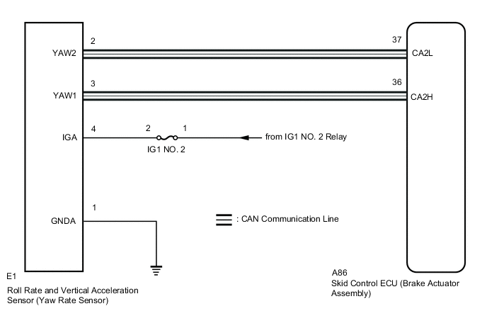
WIRING DIAGRAM
CAUTION / NOTICE / HINT
Note
-
When replacing or reinstalling the roll rate and vertical acceleration sensor (yaw rate sensor), perform zero point calibration and store system information after clearing previously calibrated data.
-
Inspect the fuses for circuits related to this system before performing the following procedure.
Tech Tips
When U110F is output together with C1459, inspect and repair the trouble areas indicated by U110F first.
PROCEDURE
-
CHECK YAW RATE SENSOR INSTALLATION
-
Check that the roll rate and vertical acceleration sensor (yaw rate sensor) has been installed properly.
OK The roll rate and vertical acceleration sensor (yaw rate sensor) is tightened to the specified torque. The roll rate and vertical acceleration sensor (yaw rate sensor) is not installed in a tilted position. Result Proceed to OK NG
NG 
INSTALL YAW RATE SENSOR CORRECTLY Click here
OK 
-
-
CHECK HARNESS AND CONNECTOR (IGA TERMINAL)
-
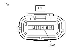
*a Front view of wire harness connector
(to Roll Rate and Vertical Acceleration Sensor (Yaw Rate Sensor))
Make sure that there is no looseness at the locking part and the connecting part of the connector.
-
Disconnect the E1 roll rate and vertical acceleration sensor (yaw rate sensor) connector.
-
Turn the engine switch on (IG).
-
Measure the voltage according to the value(s) in the table below.
Standard Voltage Tester Connection Switch Condition Specified Condition E1-4 (IGA) - Body ground Engine switch on (IG) 11 to 14 V Result Proceed to OK NG
NG
REPAIR OR REPLACE HARNESS OR CONNECTOR (IGA CIRCUIT)
OK
-
-
CHECK HARNESS AND CONNECTOR (GNDA TERMINAL)
-
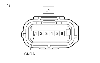
*a Front view of wire harness connector
(to Roll Rate and Vertical Acceleration Sensor (Yaw Rate Sensor))
Turn the engine switch off.
-
Measure the resistance according to the value(s) in the table below.
Standard Resistance Tester Connection Condition Specified Condition E1-1 (GNDA) - Body ground Always Below 1 Ω Result Proceed to OK NG
NG
REPAIR OR REPLACE HARNESS OR CONNECTOR (GNDA CIRCUIT)
OK
-
-
RECONFIRM DTC
-
Reconnect the E1 roll rate and vertical acceleration sensor (yaw rate sensor) connector.
-
Clear the DTCs.
Chassis > ABS/VSC/TRC > Clear DTCs -
Turn the engine switch off.
-
Start the engine.
-
Perform a road test.
-
Check if the same DTC is output.
Chassis > ABS/VSC/TRC > Trouble CodesResult Result Proceed to DTC C1459 is not output. A DTC C1459 is output. B
A
USE SIMULATION METHOD TO CHECK Click here
B
REPLACE YAW RATE SENSOR Click here
-